Hi Salar,
The basic issue. Most of the die-cast laser head bodies I have seen are milled in specific regions. They could even be investment cast for all I know. I can't imagine a way to keep the close tolerances required without some fine milling here and there. Which head are you examining? The KSS-123A? I'd have to look at one to see what you are seeing. My memories will be an aggregate of several head types over the years. That means cast or injected plastic as the basic types. I have never seen a stamped head. It might be possible that a surface milled years ago does discolour, or thread lock may be covering the surface.
-Chris
The basic issue. Most of the die-cast laser head bodies I have seen are milled in specific regions. They could even be investment cast for all I know. I can't imagine a way to keep the close tolerances required without some fine milling here and there. Which head are you examining? The KSS-123A? I'd have to look at one to see what you are seeing. My memories will be an aggregate of several head types over the years. That means cast or injected plastic as the basic types. I have never seen a stamped head. It might be possible that a surface milled years ago does discolour, or thread lock may be covering the surface.
I'll have to look at the head you are referring to. The Nak OMS-5/7 head is most definitely die-cast and milled. I am aware of the reasons fine milling is done in places.It is not milled, it is diecast. Diecasting is not as precise as milling. This is why
diecast bases of CD/DVD transports have milled surfaces where the rails or motors fit. I did not find signs of milled surfaces in the laser assembly.
The spring exists, therefore it is needed for some reason. I mentioned I wasn't certain exactly why. I'd have to take a head apart in order to even make a better guess.This would mean that the force of the spring would help in expanding!
Yes, but you can turn the tools either direction.Grating adjustment is a horizontal alignment plus turning in a clockwise manner for E-F, correct?
Yup, usually locked with thread locker.The holes of the pcb allow play, correct. Sometimes locked with theadlocker.
That would be my guess. I'm not up on optics, so I don't know what dioper means.But I guess the crucial things are done before and the alignment of the diode array is more like the dioper in your cameras´s viewfinder...?
-Chris
Hi Salar,
In a nutshell, the CD player is placed in test mode with a CD mounted, focus servo on, tracking gain off. With a probe on the TE test point (tracking error) with DC coupling you will (hopefully) see a waveform. The head is moved to a location that gives you access to the grating adjust hole, which is round. If you look into the hole with a light you will see that there is a slot with room for it to move from side to side. Looking at the tool, you can see that there is a pin, or boss that is off-center. The tool is inserted gently into the hole, then rotated with minimal pressure until if falls into the slot you observed earlier. It is possible that you have a very weak to no waveform to begin. By rotating the tool through 180°, you should see three points of maximum amplitude separated by points of minimal to no waveform. These three maximum points will have one point slightly larger than the other two. It is this center maximum waveform that you carefully adjust so it reaches it's maximum value. This can take some careful adjustments side to side. Do this carefully until the TE waveform is at it's maximum. This adjustment does determine how well the machine tracks. Usually the next step in the alignment procedure turns the tracking gain up so that the large waveform collapses to the familiar servo with low to no low frequency content. Other machines may require you to turn the tracking gain control to minimum (full CCW normally) to obtain the large tracking error waveform, or to short out the TE input point to obtain the same thing. It is critical that you follow the procedure in the service manual. Thankfully the Pioneer players have a decent alignment program. If you make a guess and short something out, you could short the servo output and either blow the output chip / transistor or semi-fuses.
I hope that helps, Chris
Okay.Please shed a light on how it was done and how the jigs worked.
In a nutshell, the CD player is placed in test mode with a CD mounted, focus servo on, tracking gain off. With a probe on the TE test point (tracking error) with DC coupling you will (hopefully) see a waveform. The head is moved to a location that gives you access to the grating adjust hole, which is round. If you look into the hole with a light you will see that there is a slot with room for it to move from side to side. Looking at the tool, you can see that there is a pin, or boss that is off-center. The tool is inserted gently into the hole, then rotated with minimal pressure until if falls into the slot you observed earlier. It is possible that you have a very weak to no waveform to begin. By rotating the tool through 180°, you should see three points of maximum amplitude separated by points of minimal to no waveform. These three maximum points will have one point slightly larger than the other two. It is this center maximum waveform that you carefully adjust so it reaches it's maximum value. This can take some careful adjustments side to side. Do this carefully until the TE waveform is at it's maximum. This adjustment does determine how well the machine tracks. Usually the next step in the alignment procedure turns the tracking gain up so that the large waveform collapses to the familiar servo with low to no low frequency content. Other machines may require you to turn the tracking gain control to minimum (full CCW normally) to obtain the large tracking error waveform, or to short out the TE input point to obtain the same thing. It is critical that you follow the procedure in the service manual. Thankfully the Pioneer players have a decent alignment program. If you make a guess and short something out, you could short the servo output and either blow the output chip / transistor or semi-fuses.
It is a basic step in setting up the swing arm. Imagine for a moment, all the angular adjustments required to keep the surface of the objective lens parallel to the surface of the CD. Additionally, there will be an error caused by the fact that the arm does not track inline with the tracks - exactly the same problem a turntable arm has with a record. It's locked in the physics of the situation, nothing you can do. So the setup of the radial swing arm must have this adjustment done simply because of the way it works. The exactness of this adjustment directly affects how well the player will track a disc. So yes, this is a permanent step in aligning any radial swing arm.I know, you have mentioned it many times. Still I wonder:
Are your experiences based on a certain period or did the nightmarish setup
last as long as the complete production run of the swingarms?
Well, yes. There was no technical reason why this adjustment wasn't fixed at the factory. It was a monetary decision in hopes to save costs. The warranty program bit back. Same reason why the lens would fall out of the laser pickup. I imagine the proper adhesive either cost more, or they were hoping to make additional money selling replacement heads. Either way, both the diffraction adjustment and lens falling out were completely avoidable problems. If I hadn't ordered the service manual on the very first machine I had to fix (not warranty authorized), the repair could not have been made. I had to fight to get them to sell me the manual for the out of warranty machine, and they gave me a bad photocopy to top things off. In Canada, Pioneer tried very, very hard to only allow their own service network service that product. But there was no reason for it, unlike some other brands where the procedure and adjustments were either very difficult or the operation of the device was quite different to the way most like devices worked (Carver amps for example). There are some products out there that only certain warranty shops were trained and authorized to repair. For those an in-house only policy made perfect sense. For normal product it didn't (Sony, Pioneer, JVC, Onkyo and others).from some point, adjusting diffraction grating was not needed anymore with Pioneer lasers.
I hope that helps, Chris
Thanks!I'm going to have to look at one around here to say much more about it. I think that somewhere I have an old one kicking around.
By rotating the tool through 180°, you should see three points of maximum amplitude separated by points of minimal to no waveform.
Uhm mmh - Does this mean, that the diffraction grating was only rotated during alignment - but never horizontally shifted and that horizontal alignment is generally not needed?
All the best, Salar
Hi Salar,
All I can say for certain is that the slotted bit is dragged from side to side by the eccentric cam action of the tool. What that does to the diffraction grating can only be guessed at.
I would think that all points of alignment are required at some point. Why it needs to be adjusted by an end-use technician is unknown to me. Probably a good thing if someone is replacing the laser diode assembly.
-Chris
You're having way too much fun taking stuff apart!
Not at all, but google indicates nobody did this before.
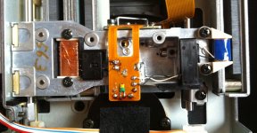
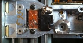
Disassembling a BU-1 today I was not lucky - Like in the KSS-123A,
a spring fits between diode and grating. This time, over the grating there
even were two washers - and the grating was NOT FIXED with threadlocker

It could move freely after the pressure of the spring was gone.
After reassembling the BU-1, the player (a CDP-102) will not read.
There is still something like a very blurred eyepattern visible, at least the diode does not seem to be killed.
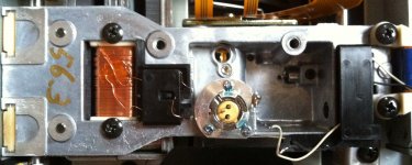
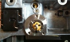
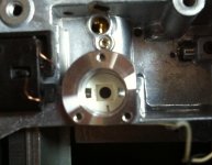
On the left side, there seems to be an allen screw that shifted the grating in place. But one can´t access it when the laser is assembled.
A second allen screw holds a tube vertically in place, that houses the diode.
Laser Diode:
Sharp LT022MC
According to this forum, it was used in the Philips CDM-0 up to CDM-4
Mechs.
Attachments
the ignoramus is back with questions and ideas...
Hi guys.
Having read most of the posts (I skim the very technical stuff as it is wasted on me) I have a few questions . Hopefully I do not embarrass my self:
Again sorry for the fundamental questions. I can say that I owned a Technics SLP8 cdp for some time and kick myself every time I think of it. I do have a couple of reasonable Sonys, a cd 505eD and a cdp950. Also a Denon cd 1300 or something similar (they're stuffed into a closet). The more I read this thread, the more depressed I get.
I could use a little help with 2 dead players I have: a Pioneer dvd player; and a Sony based Monarch "universal player (similar to the Theta Miles). Both are dvd players but suggest they can play cd. Someplace I have a review of each.Ant that are willing to help could PM me and I'll provide as many pictures or references as possible. Thanks
Hi guys.
Having read most of the posts (I skim the very technical stuff as it is wasted on me) I have a few questions . Hopefully I do not embarrass my self:
- Is it possible to check with various manufacturers to see if there are existing transports available? I've always loved the matsushita and Sony transports ( using linear motors).
- could an existing manufacturer piece together what we might want? I know there are a ferw makers of optical drives that must want to make something better, but don't really know there is a need;
- if winding our own linear motors, can we be sure the logic to drive the linear motors is out there , or does this require someone to write code for it (I can't)?
Again sorry for the fundamental questions. I can say that I owned a Technics SLP8 cdp for some time and kick myself every time I think of it. I do have a couple of reasonable Sonys, a cd 505eD and a cdp950. Also a Denon cd 1300 or something similar (they're stuffed into a closet). The more I read this thread, the more depressed I get.
I could use a little help with 2 dead players I have: a Pioneer dvd player; and a Sony based Monarch "universal player (similar to the Theta Miles). Both are dvd players but suggest they can play cd. Someplace I have a review of each.Ant that are willing to help could PM me and I'll provide as many pictures or references as possible. Thanks
Hello Nanook:
Please read the first posts - looks like the big players have left the field.
I have not planned so far but I guess writing code will be the option - being
totally independend of manufacturers who provide turnkey solutions.
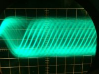
In the meantime I removed the BU-1 laser a second time. Tried to align it horizontally and put the spring and diode back in while the CDP-102 was resting on the left side - this is the side where the grating is accessible though a small hole. Theoretically it is now misaligned to the left.
After this the CDP-102 plays a CD again, though the eyepattern looks horrible.
But at least It was a first "playing around":
Here is the eyepattern after the misalignment...
Is it possible to check with various manufacturers to see if there are existing transports available?
Please read the first posts - looks like the big players have left the field.
Promise them to buy 50.000 units and they will.could an existing manufacturer piece together what we might want?
winding our own linear motors, can we be sure the logic to drive the linear motors is out there , or does this require someone to write code for it (I can't)?
I have not planned so far but I guess writing code will be the option - being
totally independend of manufacturers who provide turnkey solutions.
In the meantime I removed the BU-1 laser a second time. Tried to align it horizontally and put the spring and diode back in while the CDP-102 was resting on the left side - this is the side where the grating is accessible though a small hole. Theoretically it is now misaligned to the left.
After this the CDP-102 plays a CD again, though the eyepattern looks horrible.
But at least It was a first "playing around":
Here is the eyepattern after the misalignment...
Attachments
Hi Salar,
Go linear and forget the swing thing. Aligning one of those is a nightmare few have experience with. I tried it once and got somewhere with it, but I highly recommend that you not even consider it. It is a factory only job, and it requires very expensive jigs to perform. A perfect glass CD (just clear but of exact dimensions and zero defects) is one tool that is required. It is a basic tool for this that cannot be substituted.
-Chris
Sorry but again you are dismissing some extremely good single beam laser swing arm mechs (IMO CDM4/11 and CDM9Pro are among the best) just because of historical problems you encountered many years ago. I thought the project was to make a new/improved version ? The glass CD can be found to perform the aligning. It really is pointless to dismiss existing and proven to be good older technical stuff that had imperfections then just because of preference for stuff you repaired then that is also old now but did not have the aforementioned imperfections then (but probably/likely meanwhile has its own imperfections that turned up sooner or later or maybe it is is worn out now while the CDM4 still is playing). Sorry. Even the Wikipedia page says swing arm mechs have a longer service life compared to three beam laser linear tracking drives.
Besides, having tried "just once" is that enough to judge a product ????! Excuse me but this all seems a too easy way out to divert to classical japanese stuff just because you got trained in them, gained experience with them, got used to them. So it is safer to choose those. Personal preference, no more no less. Not an objective way of looking at engineering features/challenges.
Last edited:
Salar, there isn't any point in trying a swing arm design. Alignment is ugly as sin, and the flexible PCB that connects the head electronics to the base of the arm undergoes constant flexing while being stiffer than the type used for linear tracking mechanisms.
-Chris
Pff Chris, it really gets annoying. With this wisdom you could use less stiff flexPCB stuff now than that "they" used then ....
I am sorry but it proves that repair guys absolutely can't be objective as they only see the broken stuff which makes them very opinionated in a very short time. Let's say the broken devices they see every day are sold 20 times more than the other stuff but they receive 5 of those per week... You get the picture. Don't live in the past, we're in 2015 now.
There is a point in using a superior and elegant swing arm design: they tolerate way more damage of CD's than other mechs. A 4 mm gap is no problem for a standard El Cheapo CDM4/19.
Last edited:
Hi Salar,
There seems to be an alignment hole there, but the flexible PCB for the laser seems to be in the way. If you used wires to extend to the flexible PCB, you could probably gain access to the adjustment hole. It's okay that removing the laser releases everything because it would need to be aligned for the new laser. Sony probably had a fixture for aligning those heads on the production line.
-Chris
That's pretty good all things considered. You just showed by example how touchy that adjustment is. I guess the spring allows them to align the grating and holds it long enough for the lock bond to cure. The pressure is also needed to keep the grating in that exact horizontal plane.Here is the eyepattern after the misalignment...
There seems to be an alignment hole there, but the flexible PCB for the laser seems to be in the way. If you used wires to extend to the flexible PCB, you could probably gain access to the adjustment hole. It's okay that removing the laser releases everything because it would need to be aligned for the new laser. Sony probably had a fixture for aligning those heads on the production line.
-Chris
Hello Gentlemen!
Linear or Swing Arm - I am only the humble impresario to organize the bult
and put some money in it - not the technician to do the design.
About the glass disk - Why was it necessary? If warping was the problem,
(and not by liberate a different refractive Index) maybe some good quality
CD-Roms do the job as well? Warping should be a problem @40x speed)
As I found out, the Sharp LT022MC is used in the BU-1 mechanisms as well as
in the CDM 0-4, maybe even later swing arms (this is an assumtion I got from
this forum. Never saw it with my own eyes.
For the second goal, saving a mech, the CDMs will fall into the setup-horror anatech mentioned. But using a successor of this diode for a newly developed
linear drive (or swing arm) would give benefit to all Sharp LT022MC models
Found this on dutchaudioclassics:
"The Philips CDM9 Pro was the last Philips single-beam CD drive mechanism. Thereafter, they switched to the 3-beam linear tracking system adopted early on by Japanese manufactures. Philips chose a linear tracking construction that moved the optical lens block in a straight line because computer CD-ROM drives requiring high read speeds were in demand.
The swing arm system using a counter-weight had too much moving mass and too slow random access times for this application. In addition, because the swing arm system used in tracking error angle, it was not possible to use this system with more than a single-beam. For high-speed reading, a 3-beam system that can pick up adjacent pit streams is more advantageous.
Single-beam swing arm type drive mechanisms however are sufficient for audio only systems that do not require high speed operation. "
Link:
http://www.dutchaudioclassics.nl/philips_cdm_cd_mechanisme_list/
As I wrote before, I was in short email-contact with Lou Ottens of Philips, who developed the Compact Cassette, Laserdisc and was involved into early planning of the CD before leading the video-division of Philips.
He wrote that he did not understand why the swing arm was given up because it could be well counterbalanced, but this is no contradiction to
dutchaudioclassics.
So I assume the future proof system will be linear thinking about multiple speed applications like ripping or buffering...
Any thoughts?
Hi Salar,
Remember when I explained the exact mechanical alignment possible with the OMS-5/7 transport? Remember all those adjustments? Now imagine they are mostly wrapped up in one pivot point. All the angles in free space have to be corrected in the alignment of that pivot point and you need to check it both in close to the motor and out through the middle and the outside edge. Grab a mechanism manual for the original machines (they didn't publish one for the CDM-9 as far as I know).
I think that once Philips got a handle on the alignment, they were able to create a jig that aligned the parts and they just tightened the screws. This is a coarse alignment, not the tuned ones we saw in the original heads. By comparison, the linear mechanisms are far more tolerant of misalignment while still working passably well. I used to try and shim the more expensive players and that did improve the operation. This tool time though, and time is money. Even the OMS-5/7 came from the factory with a rough alignment. That's why I did so many, and the difference was not subtle.
The alignment procedure for the Philips transport requires the glass disc and a line source light to perform. You use sight to align things using the optics and looking through the disc to the swing arm. The alignment is very precise.
Note that some Philips transports used the same crappy motors that the rest of the world uses, so they were not more reliable as it was the failure of this motor that took most machines down, not the laser head. The top loading mechanism introduced a new failure mode to the world. The turntable would slide down the motor shaft - throwing the focus out. The mechanisms used in the Revox and Studer machines had their own pet failure mode. The suspension sagged over time to a point where it wouldn't pick up the TOC. If you adjust it so it would, then it couldn't play with the alignment that far out. I tried both turntable height and servo offset adjustments and never ended up with a working machine.
Most of the other manufacturers used mechanisms that were better made, less expensive and had a very low defect rate. They were not the same as what Philips used at all (the VAM series).
There is but one positive thing about a CDROM/DVD computer drive. They are cheap to replace, but they aren't good drives. Remember that CD error correction is different than data error correction. They may change standards later (now SATA), so the inexpensive replacement idea may well come to an end. You would have another orphan transport on your hands.
I think the linear slide motor design is the most robust, and the least noisy too. Find a good disc/spindle motor and it will run reliably for many years. This is what you want.
-Chris
Completely understood, and thankful that you are doing this. It's time for a good, reliable CD mechanism that can be serviced.Linear or Swing Arm - I am only the humble impresario to organize the bult
and put some money in it - not the technician to do the design.
The glass disk is needed to align the swing arm so that the objective lens remains parallel to the target surface of a CD during play. The dimensions are exact, a clear DVD or CD will not work as well, and a warp would be a fatal defect.About the glass disk - Why was it necessary? If warping was the problem,
(and not by liberate a different refractive Index) maybe some good quality
CD-Roms do the job as well? Warping should be a problem @40x speed)
Remember when I explained the exact mechanical alignment possible with the OMS-5/7 transport? Remember all those adjustments? Now imagine they are mostly wrapped up in one pivot point. All the angles in free space have to be corrected in the alignment of that pivot point and you need to check it both in close to the motor and out through the middle and the outside edge. Grab a mechanism manual for the original machines (they didn't publish one for the CDM-9 as far as I know).
I think that once Philips got a handle on the alignment, they were able to create a jig that aligned the parts and they just tightened the screws. This is a coarse alignment, not the tuned ones we saw in the original heads. By comparison, the linear mechanisms are far more tolerant of misalignment while still working passably well. I used to try and shim the more expensive players and that did improve the operation. This tool time though, and time is money. Even the OMS-5/7 came from the factory with a rough alignment. That's why I did so many, and the difference was not subtle.
The alignment procedure for the Philips transport requires the glass disc and a line source light to perform. You use sight to align things using the optics and looking through the disc to the swing arm. The alignment is very precise.
Note that some Philips transports used the same crappy motors that the rest of the world uses, so they were not more reliable as it was the failure of this motor that took most machines down, not the laser head. The top loading mechanism introduced a new failure mode to the world. The turntable would slide down the motor shaft - throwing the focus out. The mechanisms used in the Revox and Studer machines had their own pet failure mode. The suspension sagged over time to a point where it wouldn't pick up the TOC. If you adjust it so it would, then it couldn't play with the alignment that far out. I tried both turntable height and servo offset adjustments and never ended up with a working machine.
Not true. The mechanisms were made in China, and even the CDM-9 was problematic. Always remember that the goal at Philips was to make it as inexpensively as possible to sell and maintain. It was the CDM-9 in particular that had no support and high early failure rates. The later transports were a nightmare (the linear ones), and they were also made in China, but from an OEM manufacturer. No support and all transports had at least a 50% defect rate. Most played but with a poor eye pattern (skipped easily). New service parts had a 50% complete failure rate (they wouldn't play a CD right out of the gate).The Philips CDM9 Pro was the last Philips single-beam CD drive mechanism. Thereafter, they switched to the 3-beam linear tracking system adopted early on by Japanese manufactures.
Most of the other manufacturers used mechanisms that were better made, less expensive and had a very low defect rate. They were not the same as what Philips used at all (the VAM series).
Did you really say that Salar?maybe some good quality CD-Roms do the job as well?
There is but one positive thing about a CDROM/DVD computer drive. They are cheap to replace, but they aren't good drives. Remember that CD error correction is different than data error correction. They may change standards later (now SATA), so the inexpensive replacement idea may well come to an end. You would have another orphan transport on your hands.
Absolutely! But, access times are okay, not worried there.In addition, because the swing arm system used in tracking error angle, it was not possible to use this system with more than a single-beam.
In his shoes I might say the same thing. But his design may not be the one we see out there. His was probably much better, but the alignment nightmare is still an issue. Since he doesn't have to fix them, he probably gets a new "whatever" when the current machine shows problems. Therefore, he isn't feeling the impact of his designs.He wrote that he did not understand why the swing arm was given up because it could be well counterbalanced
I think the linear slide motor design is the most robust, and the least noisy too. Find a good disc/spindle motor and it will run reliably for many years. This is what you want.
-Chris
Of course a newly designed swing arm mech would not have all those problems, it would also have a reliable brushless spindle motor. It would have a better laser too as we're decades further in time so we are ought to be able to obtain reliable and relatively simple single beam laser diodes. It would also have nothing to do with Philips at all, not with regards to reliability, support or whatever troublesome features old devices and their suppliers possibly have had some 30 to 35 years ago. It could be made mechanically so precise that in player alignment would not be necessary or ... that alignment would be done electronically...I have had at least one CD player with electronic adjustment but I forgot what brand and type.
It would be a swing arm mech with all the advantages a swing arm has and with most classical errors reduced to a minimum. Who has thought about combining Stable Platter and swing arm for instance ? We better stop looking in the past too much and design according what is available and what is realistic according 2015 knowledge. That having said...if it is not the mechanical side it will be the electronic side that will pose some serious challenges.
It could even be designed so good and produced so cheap that servicing might be that buying a new replacement one would opt out servicing at all as customary in this day and age.
I think you are now really making unjust assumptions and underestimate the knowledge of the (then) Philips NatLab. You also talk in the present tense while we are talking about an invention of 35 years ago. We better keep good contacts with the inventors of these devices, out of courtesy and as we might need their help !
https://en.wikipedia.org/wiki/Philips_Natuurkundig_Laboratorium
https://web.archive.org/web/20141104160226/http://www.exp-math.uni-essen.de/~immink/pdf/cdstory.htm
It would be a swing arm mech with all the advantages a swing arm has and with most classical errors reduced to a minimum. Who has thought about combining Stable Platter and swing arm for instance ? We better stop looking in the past too much and design according what is available and what is realistic according 2015 knowledge. That having said...if it is not the mechanical side it will be the electronic side that will pose some serious challenges.
It could even be designed so good and produced so cheap that servicing might be that buying a new replacement one would opt out servicing at all as customary in this day and age.
In his shoes I might say the same thing. But his design may not be the one we see out there. His was probably much better, but the alignment nightmare is still an issue. Since he doesn't have to fix them, he probably gets a new "whatever" when the current machine shows problems. Therefore, he isn't feeling the impact of his designs.
I think you are now really making unjust assumptions and underestimate the knowledge of the (then) Philips NatLab. You also talk in the present tense while we are talking about an invention of 35 years ago. We better keep good contacts with the inventors of these devices, out of courtesy and as we might need their help !
https://en.wikipedia.org/wiki/Philips_Natuurkundig_Laboratorium
https://web.archive.org/web/20141104160226/http://www.exp-math.uni-essen.de/~immink/pdf/cdstory.htm
Last edited:
As I wrote before, I was in short email-contact with Lou Ottens of Philips, who developed the Compact Cassette, Laserdisc and was involved into early planning of the CD before leading the video-division of Philips.
He wrote that he did not understand why the swing arm was given up because it could be well counterbalanced, but this is no contradiction to
dutchaudioclassics.
Salar, the sole reason the swing arm mechs were given up was that they were way more expensive to produce than the 3 beam mechs. Please note that they were made in Europe (just like the TDA wafers) for many years which made it even harder to compete.
Last edited:
Hi jean-paul,
Constant linear velocity vs constant angular velocity.
-Chris
Not so. You are stuck with the physics of the design. That alignment is a part of the swing arm design just as the fact that the arm swings.Of course a newly designed swing arm mech would not have all those problems
As every option would. I expect to use the better motors and lasers in either design. The laser is the same for either model, so those differences null out.it would also have a reliable brushless spindle motor. It would have a better laser too as we're decades further in time so we are ought to be able to obtain reliable and relatively simple single beam laser diodes.
You are stuck with the accuracy of the laser diode assembly. These arms were already cast and milled to close tolerances. The only thing you can improve on would be the laser diode assembly. If even one part of the alignment remains to be done, it will probably be a factory only deal ... breaker.It could be made mechanically so precise that in player alignment would not be necessary or ... that alignment would be done electronically...I have had at least one CD player with electronic adjustment but I forgot what brand and type.
Can't. They did their best with release # 1 and couldn't get away from that. Labour is expensive and Philips is all about being cheap. You want to believe they exhausted every single avenue possible or imagined. You are stuck with the physics of the situation.It would be a swing arm mech with all the advantages a swing arm has and with most classical errors reduced to a minimum.
Many, it doesn't work. The physics of the way a CD works is in direct conflict with anything that increases the rotating mass. The speed has to change, sometimes quickly. It isn't a turntable, so don't try to deal with it as it is.Who has thought about combining Stable Platter and swing arm for instance ? We better stop looking in the past too much and design according what is available and what is realistic according 2015 knowledge.
Constant linear velocity vs constant angular velocity.
-Chris
Hi jean-paul,
But, what adjustment comes first? Mechanical or electronic? Mechanical is with the electronics set for the perfect case (servo offsets to zero and mid gain). Once the mechanical is done, then you can adjust the electronic part.
This business model only hurts the average person. I feel it is irresponsible and a class action lawsuit should have been brought against Philips. Maybe they settled one and kept it quiet?
In a nutshell. The laser and disc motor is the same no matter which direction you go. The three beam head can be adjusted in the field, transport alignment is also possible to bring out the best performance. The swing arm will always have difficult alignment and a tangential error because of the arc of the arm. Both mechanisms are quiet in operation. So it comes down to one not being field adjustable (call it moving coil without a superior sound) and the other easy optimization in the field (moving magnet I guess, but with the same quality). I don't see any rational choice but linear. Just like in the free market, the linear mech won out, but high quality versions of either died off.
-Chris
Most new machines are self adjusting on the fly.that alignment would be done electronically...I have had at least one CD player with electronic adjustment but I forgot what brand and type.
But, what adjustment comes first? Mechanical or electronic? Mechanical is with the electronics set for the perfect case (servo offsets to zero and mid gain). Once the mechanical is done, then you can adjust the electronic part.
You must work at Philips to suggest this. That is right out of their playbook, except the transports are not inexpensive to the consumer. Please try to forget the throwaway society. Otherwise just buy whatever everyone else buys, you don't need a good machine.It could even be designed so good and produced so cheap that servicing might be that buying a new replacement one would opt out servicing at all as customary in this day and age.
What came out of that group was an unserviceable nightmare. Then they set about dropping the quality of that nightmare until they ended up accepting cheap Chinese mechanisms that had no quality control. They just turned out the lights and left the room. The most intelligent thing they did as a group was to distance themselves from that mess they made.I think you are now really making unjust assumptions and underestimate the knowledge of the (then) Philips NatLab.
Has the physics changed? Nope. Therefore the situation of however long ago is still current. That is why I talk about it in the present tense.You also talk in the present tense while we are talking about an invention of 35 years ago.
Well, a three beam mech can be identical to a single beam mech. Both Salar and I own an example of single beam, linear tracking mechanisms. What was expensive was the transport and how precise it had to be to simply work. That mechanism has a built in tangential error so that a three beam head assembly can't work in it. They are locked into a single beam that also suffers from the same problem. However, the lack of the E-F diodes means it isn't that critical, the focus angle still changes on the quad pickup diode and is simply a problem they can live with. I think what happened was that they got to a point where the transport could not be made any cheaper and still work, they were forced to move to a linear design. Of course, they were selling the most expensive mechanism for their time and could have maintained the quality. But then the other cost would bear down on them. Support. They refused to support their clients, and in turn you and I.Salar, the sole reason the swing arm mechs were given up was that they were way more expensive to produce than the 3 beam mechs.
This business model only hurts the average person. I feel it is irresponsible and a class action lawsuit should have been brought against Philips. Maybe they settled one and kept it quiet?
In a nutshell. The laser and disc motor is the same no matter which direction you go. The three beam head can be adjusted in the field, transport alignment is also possible to bring out the best performance. The swing arm will always have difficult alignment and a tangential error because of the arc of the arm. Both mechanisms are quiet in operation. So it comes down to one not being field adjustable (call it moving coil without a superior sound) and the other easy optimization in the field (moving magnet I guess, but with the same quality). I don't see any rational choice but linear. Just like in the free market, the linear mech won out, but high quality versions of either died off.
-Chris
Not the best system wins, it is always the cheapest system that wins the market.
Check VHS, RJ45 etc.
If you read the links you can read why Philips had other priorities at that time. They were not far from bankrupt. They did not cooperate with Sony for no reason. They made some very good products and made some very bad business decisions. I am thankful for the guys in the lab that did the hard work on CD mechs and the DAC chips. We still enjoy their work. If they just would have chosen 18 or 20 bit but that was technically impossible then...
I leave this thread for what it is. As an engineer I think one should not keep looking at problems of the past but learn from them and embrace technical challenges (and find new solutions). If we would think like repair guys there would have been no CD system at all.
Last edited:
- Home
- Source & Line
- Digital Source
- Quality CD-Mechanisms are long gone - let us build one ourselves!