I have a few thoughts. Salar started this with a particular goal in mind. A universal CD/DVD mechanism as a replacement part for worn out players. As you pointed out in your last post, it is going to be difficult to match servo's and motors. Plus I don't see how you are going to sell something like this.
My idea is to design a complete new player.
My idea is to design a complete new player.
Anatech, If you are doing glass-mastering or replication, you would want to know the jitter per land and pit type. 3T and 11T pits could be short while the 5T pits are long or T3 pits short while the T3 lands are long.
Anyone wanting to test their discs can try Opti Drive Control website
Check that you have the correct drive before downloading, there is a 1 month free test period.
Anyone wanting to test their discs can try Opti Drive Control website
Check that you have the correct drive before downloading, there is a 1 month free test period.
Maybe both Ideas, building a complete new player and saving old machines can be still combined.
I was playing around with a CDP-502 today (identical to 552 / 620 /650), especially with the BU-1c mechanism. That thing lay on the attic for some years, the rods were dry. But it still needed one second to jump from the first to the last track because of the linear drive. Laser power / eyepattern is low, around 0,8V on the scope.
Opened the head for cleaning the lens and upper collimation lens underneath and was surprised to see that the design of the upper lens´mechanics is the same as in the KSS-123A. But the design of the collimation lens looked different as well as cylindrical lend and PD array.
This is my dream - reliable, no gear wear out, and still after 31 years without probably any service. Brushless motor with at least a 3mm shaft.
None of the temporary designs is prepared for brushless!
Thus a cheapo providing the circuitry would call for a cheap "brusher" anway - correct? (O.k checked this also. Of course one can get a good replacemment fro a common Mabuchi, which has the same data)
To revive the technology of linear mechs would be a big selling argument to me. It is unique and can be sturdy and reliable.
Almost everything in this mech would be based on magnets and coils.
Very intriguing that one never would have to think about finding a certain gear as replacement but could probably wind a new coil.
And after 30 years, i.e knowledge about linear drives has become common, and there are forums about building them.
I tried the same by reviving the swing arms in another thread, but seems to be too complicated. (And Chris hates them )
)
Now, why combining both worlds? Let´s say, a KSS-123A (or better it´s optical assembly and mech) can be completely copied, the new laser would have to replace the obsolete SLD104 variants.
According to this forum, this diode was used in many KSS-types.
As a side effect, replacement of old diodes of this type in original lasers could be also researched.
What do you think?
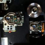
Attached a photograph of the unnamed BU-1 laser (on the left) next to a KSS-123A
All the best,
Salar
I was playing around with a CDP-502 today (identical to 552 / 620 /650), especially with the BU-1c mechanism. That thing lay on the attic for some years, the rods were dry. But it still needed one second to jump from the first to the last track because of the linear drive. Laser power / eyepattern is low, around 0,8V on the scope.
Opened the head for cleaning the lens and upper collimation lens underneath and was surprised to see that the design of the upper lens´mechanics is the same as in the KSS-123A. But the design of the collimation lens looked different as well as cylindrical lend and PD array.
This is my dream - reliable, no gear wear out, and still after 31 years without probably any service. Brushless motor with at least a 3mm shaft.
None of the temporary designs is prepared for brushless!
Thus a cheapo providing the circuitry would call for a cheap "brusher" anway - correct? (O.k checked this also. Of course one can get a good replacemment fro a common Mabuchi, which has the same data)
To revive the technology of linear mechs would be a big selling argument to me. It is unique and can be sturdy and reliable.
Almost everything in this mech would be based on magnets and coils.
Very intriguing that one never would have to think about finding a certain gear as replacement but could probably wind a new coil.
And after 30 years, i.e knowledge about linear drives has become common, and there are forums about building them.
I tried the same by reviving the swing arms in another thread, but seems to be too complicated. (And Chris hates them
)Now, why combining both worlds? Let´s say, a KSS-123A (or better it´s optical assembly and mech) can be completely copied, the new laser would have to replace the obsolete SLD104 variants.
According to this forum, this diode was used in many KSS-types.
As a side effect, replacement of old diodes of this type in original lasers could be also researched.
What do you think?
Attached a photograph of the unnamed BU-1 laser (on the left) next to a KSS-123A
All the best,
Salar
Attachments
definitely out of my league here...but...
thought I'd add my (completely) uninformed opinion.
Are there no good quality transport mechanisms out there anymore?I recall years ago NEC multispin CD/dvd drives were sought after due to their availability and quality. Attached to whatever DAC at the time and it was promoted as a reference quality player. Is NEC out of business or have stopped cd/dvd drive manufacturing? I like the idea of procurring an existing piece and improving it if need be.
Of course I know nothing, and am certainly not a tech, but it seems to me that utilizing existing technology where appropriate is a no-brainer. I have a stack of the old Sony SCHP-1001 based "grey" stations that I can use. Ugly to look at but very robust. I also have a Sony transport from a Lincoln, when JBL/Harmon was doing Lincoln's Premium sound systems. The transport was a Sony and appears to be robustly built and high quality.
I own a few older cd players that pretty much read everything. I use a Pioneer PD-54 daily and have done so for 20 years or so. The transport may not be a KSS123A or KSS151, or any of the Phillips CDM sees, but it continues to spin. I dread the day that it stops.
So what do we do? I'd love to get my hands on a Nakamichi OMS5, OMS7 or even the cd Player 4 or better. I still can't believe there are no good quality transports out there. What about the Goldman "rip off" transport (using a Pioneer drive)?
Sorry if I'm simply too ignorant to get the point of starting with the laser assembly, then adding the drive.
It looks like quality/reliability is gone. Read my first post. I have shelved some KSS-123A, bought the last two available for reasonable prices around 2000 for Nakamichi OMS-5II. The OMS-5EII got "updated" with toroidal transformers and Buffallo DAC in 2006. Even got SPDIF inputs to serve as DAC (The player circuitry can be switched off, the power button serves as input selector for 6 digital sources) First Pioneer made "Super Drives" for Macintosh G4 were mechanical dreams amd able to rip DVD´s with heavy artificial defcets.
Still use one for heavily scratched DVDs/CD´s where other Rom drives fail.
Another hint that quality declined: Instead of having long production runs for
first/ second generation lasers for desktop players, new ones were developed almost every year, and the the evolution did not serve to make them better but to reduce production costs. All the best, Salar
Hi Salar,
Watch the copy of the KSS-123A be more reliable.
On production runs. Long production runs are the least expensive way to supply and support a product. There aren't enough breakthroughs to warrant replacing a production lines tooling and station set up.
There is one single thing that has changed. They have removed the skill from a service technician's job (and they still screw up). The result is mediocre performance that is accepted. The cheap and nasty equipment improved considerably while the ability to obtain very good performance was eliminated. At least the junk works, but the people who see value and performance in better equipment are shut out. Your goal as I recall was to produce a machine capable of very high performance while learning from earlier mistakes to also gain a long life. Just like stereos used to be (and what the public expected).
Heads like the Sanyo SF-91 can give great eye patterns, and are cheap. Their one defect was the design for the slide rod. So eliminate that and substitute something like the Sony KSS-151A or the Technics linear motor. They are both very reliable and also very quick and silent in operation. So gears and belts are designed out of the CD Mechanism. The disc motor should have a balance of mass and lightness. A low mass to be able to change speed quickly without tearing up any bearings and the mass to run smoothly. The disc itself is the flywheel. Magnetic clamping to eliminate a point of contact to the mechanism (standard with Sony and Technics drives), so no more flapper bearings. Except for the head, we are designing a Denon x560 machine. These were very good.
I would recommend tray loading and certainly not direct hand loading. Tray loading belts would prevent damage from bad position switches or optical (yes!) sensors. Worm gear drive can transfer extremely high levels of force and are therefore not recommended.
The basic transport chassis should be either die cast and milled with Al or composite materials (Denon). If these parts already exist we should try to use them, otherwise settle on a design that can accommodate different laser pickup designs and possibly disc motors. Above anything, the design should hopefully never need to be redesigned or changed.
-Chris
Hi Mark,
For a production environment for making CD or DVD discs, you have the expertise needed, I don't. All I can do is comment on the end product where it impacts the playing process from the earlier good discs when playback was more optimal. I'm not saying all new discs are bad, or all old ones were good. But the obvious problems (translucent, poor mirroring) were the minority rather than the rule.
I find that today's discs have lower RF levels and poorer pit shape (okay, pit / land) than ever before. I don't know which products your plant produces, but I could tell very quickly whether they were good or not.
The eye pattern and envelope can tell me almost everything I need to know about the CD. Looking at the servo outputs can shed a little more light on things.
-Chris
Chris, you may be right about new/old discs. That would also depend on your definition. With a possibly lower RF signal the newer discs still have lower error rates.
I really wanted to stay out of a discussion on disc quality as not to repeat the RF/Error-Correction discussion. That is the reason I didn't respond to previous remarks on coating.
You have spend years looking at eye-patterns, then somebody comes along and starts claiming that error rates and its data are also important.
Hi Chris and Mark,
about combining both worlds (Copying a KSS-Assembly and exploring the
possibility of saving original assemblies using new diodes):
Dug further in my KSS-123A assembly (See also posti#80):
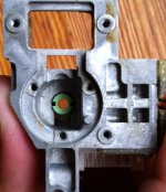
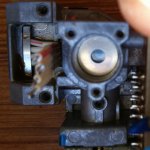
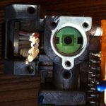
I assume the pressure of the spring underneath the diode is not related in function to the diode itself but helped aligning the diffraction grating.
Between the grating and spring is a smooth washer, with a little bit of threadlocker.
I assume a threadlocker was needed to make the alignment stable against
vibrations (during transport) but it would work without threadlocker.
Big question:
In a Sony 3 beam laser, how and on which step of the assembling was this alignment made?
Is the alignment of the grating really crucial in relation to the laser diode AND the following optical assembly. Or to the diode only?
No alignment possible for a human when the mirror and collimation lenses are put in. Know what I mean? Its sink or swim with the other parts,
besides aligning the astigmatic lens leading the beam to the photodiodes.
Could be that the assembly with the front lens also can be aligned, because the through holes for the screws allow some play.
Some photos of the grating, even the grooves can be seen in one macro shot
Any thoughts?
about combining both worlds (Copying a KSS-Assembly and exploring the
possibility of saving original assemblies using new diodes):
Dug further in my KSS-123A assembly (See also posti#80):
I assume the pressure of the spring underneath the diode is not related in function to the diode itself but helped aligning the diffraction grating.
Between the grating and spring is a smooth washer, with a little bit of threadlocker.
I assume a threadlocker was needed to make the alignment stable against
vibrations (during transport) but it would work without threadlocker.
Big question:
In a Sony 3 beam laser, how and on which step of the assembling was this alignment made?
Is the alignment of the grating really crucial in relation to the laser diode AND the following optical assembly. Or to the diode only?
No alignment possible for a human when the mirror and collimation lenses are put in. Know what I mean? Its sink or swim with the other parts,
besides aligning the astigmatic lens leading the beam to the photodiodes.
Could be that the assembly with the front lens also can be aligned, because the through holes for the screws allow some play.
Some photos of the grating, even the grooves can be seen in one macro shot
Any thoughts?
Attachments
...i know the objective here is another, nevertheless there is interest reading this i think, on what can be created from a milled CDM4 mech.
http://www.diyaudio.com/forums/vendors-bazaar/122247-my-cdm4-player.html
http://www.diyaudio.com/forums/vendors-bazaar/122247-my-cdm4-player.html
Hi Mark,
I think we both are having an instance of culture shock as far as our respective worlds look like. If Salar does move ahead on this concept, your input would be extremely valuable. How better to design the error responses than an expert in that area. In other words, once the data read goes all pear-shaped, how best to counter the problems? I can only concentrate on trying to retrieve that data in the analog areas. Once the RF amp has generated the EFM signal, I'm totally out of my element. Then someone else needs to carry the ball. I'm an analog guy (analog technician) at heart. I can deal with digital faults, but I can't design with it, or improve anything in the digital realm other than the clock (ovenized or temperature compensated would be my choice). I have to wait until an analog signal reappears before I can be useful again.
Cheers, Chris
Well, they are. Even more so in the development of a new device. Once the design is completed the importance of looking at error rates becomes less unless you are having a problem in that area.You have spend years looking at eye-patterns, then somebody comes along and starts claiming that error rates and its data are also important.
I think we both are having an instance of culture shock as far as our respective worlds look like. If Salar does move ahead on this concept, your input would be extremely valuable. How better to design the error responses than an expert in that area. In other words, once the data read goes all pear-shaped, how best to counter the problems? I can only concentrate on trying to retrieve that data in the analog areas. Once the RF amp has generated the EFM signal, I'm totally out of my element. Then someone else needs to carry the ball. I'm an analog guy (analog technician) at heart. I can deal with digital faults, but I can't design with it, or improve anything in the digital realm other than the clock (ovenized or temperature compensated would be my choice). I have to wait until an analog signal reappears before I can be useful again.
Cheers, Chris
Hi Salar,
You're having way too much fun taking stuff apart!
The KSS-151A style head has less mass and may also be repairable. Within reason, a lighter head assembly might serve us better.
-Chris
You're having way too much fun taking stuff apart!
You have me there. These things are done in the factory and are locked long before we see them. The guys selling the lasers might be able to tell you. I honestly don't know and don't have a clue.about combining both worlds (Copying a KSS-Assembly and exploring the
possibility of saving original assemblies using new diodes):
It could also be involved in having the laser maintain a good thermal contact with the housing / heat sink. It wouldn't surprise me to see there are multiple reasons for that one spring.I assume the pressure of the spring underneath the diode is not related in function to the diode itself but helped aligning the diffraction grating.
Good question, but one never knows. It may maintain contact as the temperature changes causing the dimensions of the head to change.I assume a threadlocker was needed to make the alignment stable against
vibrations (during transport) but it would work without threadlocker.
To the entire optical path including the alignment of the laser.Is the alignment of the grating really crucial in relation to the laser diode AND the following optical assembly. Or to the diode only?
They may have a clever tool, or the other adjustments are there to compensate for manufacturing tolerances. If you can't adjust their alignment, I guess everything else has to be adjustable. I imagine there are some tight dimensional requirements for those parts and the head casting in those areas. Maximizing yield would not be ignored.No alignment possible for a human when the mirror and collimation lenses are put in. Know what I mean? Its sink or swim with the other parts,
besides aligning the astigmatic lens leading the beam to the photodiodes.
I'm not sure. I disturbed that alignment when I fixed my own laser head. It didn't seem to cause any problems with the eye pattern. Maybe I was lucky?Could be that the assembly with the front lens also can be aligned, because the through holes for the screws allow some play.
If you go for the KSS-123A, are you going for the linear slide motor, or gear drive?Any thoughts?
The KSS-151A style head has less mass and may also be repairable. Within reason, a lighter head assembly might serve us better.
-Chris
Hi Chris!
One can´t access the diffraction grating when the mirrors and collimation lenses are put atop. I.e. he grating has two nuts on the top to turn it, no room for tools when the mirors and collimatinlenses are put in.
As far as I understand, the collimation lens puts the 3 split beams in parallel.
Without, they would spread equally with distance. If you had reference point for the center beam, aligning the side beams should be easy when pointig at a distant object - at least that is my amateurish understanding.
Another point: The diode fits tight in the aluminium laser housing without the spring already. The spring does not help in dissipation at all.
I think we need some expertise from some Pioneer folks here, because they had to align the grating in early Pioneer players
@Ceevee:
I started this thread:
http://www.diyaudio.com/forums/digi...nting-swing-arm-mechanism-looking-allies.html
No solution up to the moment right now.
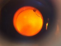
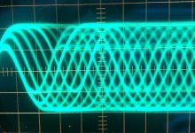
I have two players @home with Sony´s Linear Transport - love them -clean eyepattern, (but low on one machine, watch images, scope is @0.2V) quick access, no gears, running for 30 years now.
BTW- look for what the rotating CD reflects in the photo of the linear drive mech
O.K, now some basic thoughts about the Pros and Cons:
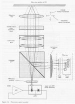
Pro for 3 Beam- most common, but con: aligning of diffraction grating is a problem.
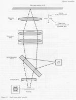
Single beam - as far as I understand, pro for simpler optics.
Linear motor or gear - Pro for linear, because we´ll have to deal with buying magnets and winding coils anyway.
Maybe a general con for sled drives, unmentioned yet: Always two servos working stacked, sled and lens.
Pro this would be a pro for the swing arm: Only one servo for tracking.
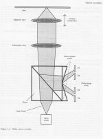
I attached the schematics for each principle, taken from the excellent book
"Understanding and Servicing CD Players" by Ken Clements, the best source for me besides "Sam´s Laser Repair FAQ".
Should we give the swing arm another thought? I would have the chance to get a Grundig player from 1984 for a few bucks...
But again, besides swing arm, linear would be my other favourite.
One can´t access the diffraction grating when the mirrors and collimation lenses are put atop. I.e. he grating has two nuts on the top to turn it, no room for tools when the mirors and collimatinlenses are put in.
As far as I understand, the collimation lens puts the 3 split beams in parallel.
Without, they would spread equally with distance. If you had reference point for the center beam, aligning the side beams should be easy when pointig at a distant object - at least that is my amateurish understanding.
Another point: The diode fits tight in the aluminium laser housing without the spring already. The spring does not help in dissipation at all.
I think we need some expertise from some Pioneer folks here, because they had to align the grating in early Pioneer players
@Ceevee:
I started this thread:
http://www.diyaudio.com/forums/digi...nting-swing-arm-mechanism-looking-allies.html
No solution up to the moment right now.
I have two players @home with Sony´s Linear Transport - love them -clean eyepattern, (but low on one machine, watch images, scope is @0.2V) quick access, no gears, running for 30 years now.
BTW- look for what the rotating CD reflects in the photo of the linear drive mech
O.K, now some basic thoughts about the Pros and Cons:
Pro for 3 Beam- most common, but con: aligning of diffraction grating is a problem.
Single beam - as far as I understand, pro for simpler optics.
Linear motor or gear - Pro for linear, because we´ll have to deal with buying magnets and winding coils anyway.
Maybe a general con for sled drives, unmentioned yet: Always two servos working stacked, sled and lens.
Pro this would be a pro for the swing arm: Only one servo for tracking.
I attached the schematics for each principle, taken from the excellent book
"Understanding and Servicing CD Players" by Ken Clements, the best source for me besides "Sam´s Laser Repair FAQ".
Should we give the swing arm another thought? I would have the chance to get a Grundig player from 1984 for a few bucks...
But again, besides swing arm, linear would be my other favourite.
Attachments
Last edited:
Hi Salar,
Go linear and forget the swing thing. Aligning one of those is a nightmare few have experience with. I tried it once and got somewhere with it, but I highly recommend that you not even consider it. It is a factory only job, and it requires very expensive jigs to perform. A perfect glass CD (just clear but of exact dimensions and zero defects) is one tool that is required. It is a basic tool for this that cannot be substituted.
-Chris
Hi Salar,
Okay, here goes to the best of my ability and knowledge.
The swing arm needs a sine wave injected into the tracking servo in order to create an error. The edges of the track cause a signal strength drop off and all it does is balance the two. However, the swing arm is driven by yet another servo - just like a linear tracking system. So it suffers from the same issue the linear tracking models do. There is no advantage for either system as far as number of tracking servos is concerned. One point for the linear system. The swing arm should naturally seek the center of it's arc travel. So the servo must constantly act against this force one way, then past the center, the other way. This takes power. Even with the linear motor version of the linear tracking system has less force to correct for.
Salar, there isn't any point in trying a swing arm design. Alignment is ugly as sin, and the flexible PCB that connects the head electronics to the base of the arm undergoes constant flexing while being stiffer than the type used for linear tracking mechanisms.
-Chris
Okay, here goes to the best of my ability and knowledge.
Which can only mean that either the adjustments are done before the top is installed, or it depends completely on the accuracy of the milled surfaces it rests against.One can´t access the diffraction grating when the mirrors and collimation lenses are put atop. I.e. he grating has two nuts on the top to turn it, no room for tools when the mirors and collimatinlenses are put in.
Yes, but I'm not sure how easy aligning the E and F beams would be doing it that way. I would bet that the lens are tightly specified for characteristics and we are once again back to close tolerance milling. This would be more reliable over time and there is some latitude in the adjustments to correct for this. Probably in the mounting of the pickup diode array which you can see is adjusted.As far as I understand, the collimation lens puts the 3 split beams in parallel.
Without, they would spread equally with distance. If you had reference point for the center beam, aligning the side beams should be easy when pointig at a distant object
Parts never exist in high volume parts that aren't absolutely necessary. Therefore the spring provide a critical function. I'm going to bet that the spring maintains pressure on the laser diode assembly to hold it tightly into alignment during periods where the casting is expanded, like when it is warm. Maybe it is most useful in very hot climates where the extra heat does cause the dimensions in the casting to shift enough to throw off the alignment. A spring would compensate for these changes by applying pressure. So something is being held at one end or the other. The laser assembly may well become loose in it's channel when warm, allowing free motion back and forth. Maybe it's the other end. I honestly do not know, but I can say with certainty that the part is required. Maybe it is only used while adjustments are being made and until the lock bond sets - but then it can't be removed. Who knows?The diode fits tight in the aluminium laser housing without the spring already. The spring does not help in dissipation at all.
Yes, I have aligned many. Also Yamaha heads and the Nak OMS-2 if memory serves. I have used the alignment tools for this on other brands when needed. Aligning the diffraction grating isn't a job one looks forward to doing, at least not doing it well. Everyone else's heads could be installed and they would work, but the Pioneer heads were guaranteed to not work without this adjustment being made. This adjustment would determine how well the machine tracked defects and overall RF signal amplitude. What a waste of everyone's time for something that should have been done in the factory.I think we need some expertise from some Pioneer folks here, because they had to align the grating in early Pioneer players
Not really. The sled motor is merely a low pass filtered signal from the tracking servo. It's dead easy and simple in operation. The sled servo has no choice but to track with the tracking servo except for the kick pulse to skip tracks.Maybe a general con for sled drives, unmentioned yet: Always two servos working stacked, sled and lens.
Pro this would be a pro for the swing arm: Only one servo for tracking.
The swing arm needs a sine wave injected into the tracking servo in order to create an error. The edges of the track cause a signal strength drop off and all it does is balance the two. However, the swing arm is driven by yet another servo - just like a linear tracking system. So it suffers from the same issue the linear tracking models do. There is no advantage for either system as far as number of tracking servos is concerned. One point for the linear system. The swing arm should naturally seek the center of it's arc travel. So the servo must constantly act against this force one way, then past the center, the other way. This takes power. Even with the linear motor version of the linear tracking system has less force to correct for.
Salar, there isn't any point in trying a swing arm design. Alignment is ugly as sin, and the flexible PCB that connects the head electronics to the base of the arm undergoes constant flexing while being stiffer than the type used for linear tracking mechanisms.
-Chris
Dear Chris,
It is not milled, it is diecast. Diecasting is not as precise as milling. This is why
diecast bases of CD/DVD transports have milled surfaces where the rails or motors fit. I did not find signs of milled surfaces in the laser assembly.
Grating adjustment is a horizontal alignment plus turning in a clockwise manner for E-F, correct? The spring would only work vertically.
The holes of the pcb allow play, correct. Sometimes locked with theadlocker.
But I guess the crucial things are done before and the alignment of the diode array is more like the dioper in your cameras´s viewfinder...?
Please shed a light on how it was done and how the jigs worked.
Please do not forget: Second goal on this thread is to successfuly swap
laser diodes, probably with their own APC installed this means knowledge
how to do the grating adjustment.
Thus not only build a new laser assembly - but use the knowledge to save those great machines built in the first 10 years.
I know, you have mentioned it many times. Still I wonder:
Are your experiences based on a certain period or did the nightmarish setup
last as long as the complete production run of the swingarms?
I.e, from some point, adjusting diffraction grating was not needed anymore with Pioneer lasers. Servicing hours cost money...
All the best,
Salar
Which can only mean that either the adjustments are done before the top is installed, or it depends completely on the accuracy of the milled surfaces it rests against.
It is not milled, it is diecast. Diecasting is not as precise as milling. This is why
diecast bases of CD/DVD transports have milled surfaces where the rails or motors fit. I did not find signs of milled surfaces in the laser assembly.
This would mean that the force of the spring would help in expanding!I'm going to bet that the spring maintains pressure on the laser diode assembly to hold it tightly into alignment during periods where the casting is expanded, like when it is warm.
Grating adjustment is a horizontal alignment plus turning in a clockwise manner for E-F, correct? The spring would only work vertically.
Probably in the mounting of the pickup diode array which you can see is adjusted.
The holes of the pcb allow play, correct. Sometimes locked with theadlocker.
But I guess the crucial things are done before and the alignment of the diode array is more like the dioper in your cameras´s viewfinder...?
I have used the alignment tools for this on other brands when needed. Aligning the diffraction grating isn't a job one looks forward to doing, at least not doing it well. Everyone else's heads could be installed and they would work, but the Pioneer heads were guaranteed to not work without this adjustment being made. This adjustment would determine how well the machine tracked defects and overall RF signal amplitude. What a waste of everyone's time for something that should have been done in the factory.
Please shed a light on how it was done and how the jigs worked.
Please do not forget: Second goal on this thread is to successfuly swap
laser diodes, probably with their own APC installed this means knowledge
how to do the grating adjustment.
Thus not only build a new laser assembly - but use the knowledge to save those great machines built in the first 10 years.
Go linear and forget the swing thing. Aligning one of those is a nightmare few have experience with. I tried it once and got somewhere with it, but I highly recommend that you not even consider it. It is a factory only job, and it requires very expensive jigs to perform. A perfect glass CD (just clear but of exact dimensions and zero defects) is one tool that is required. It is a basic tool for this that cannot be substituted.
I know, you have mentioned it many times. Still I wonder:
Are your experiences based on a certain period or did the nightmarish setup
last as long as the complete production run of the swingarms?
I.e, from some point, adjusting diffraction grating was not needed anymore with Pioneer lasers. Servicing hours cost money...
All the best,
Salar
Sorry, I forgot to mention how I judge
milled surfaces drom diecast surfaces:
Diecast aluminiums are dull, rough and grey.
Maybe because the hot aluminium reacts stronger
with the air's oxygen.
Milled is shiny and smooth. When you mill diecast material,
the milled surface will become -and stay-smooth and shiny.
You see that in the threadholes of the laser.
Last edited:
- Home
- Source & Line
- Digital Source
- Quality CD-Mechanisms are long gone - let us build one ourselves!