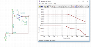
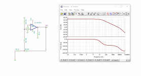
Use the fig. 1 circuit in this paper. https://waset.org/publications/1000...loop-voltage-gain-of-an-operational-amplifier
Maybe my output should be at the voltage divider and not the output?
The circuit looks ok. Are you using the right model for the amplifier?
What happens when you feed the input signal to the positive input instead,
with everything else the same?
Last edited:
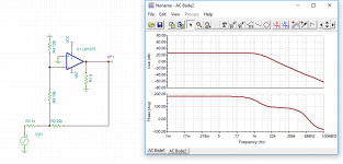
Here it is reversed:
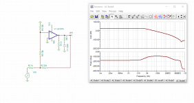
I got the mode from: LM1875 20-W Audio Power Amplifier | TI.com
and what if I am using the wrong input source? I been trying using a sine wave with an Amplitude of 1 at 1khz ?

I got the mode from: LM1875 20-W Audio Power Amplifier | TI.com
and what if I am using the wrong input source? I been trying using a sine wave with an Amplitude of 1 at 1khz ?
Here it is reversed
No, that's positive feedback. Use the exact same circuit, but connect the source to the + amp input, instead of to the 1k. Ground the end of the 1k that was formerly connected to the source.
Last edited:
I hate bothering you but thank you once again for helping me as I have 2 more questions after this.
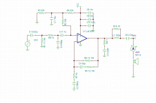
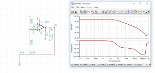
What I meant was, without C11 the voltage divider falls apart meaning the VCC voltage no longer sees R3 R4 as the voltage divider network, but sees R3 R4 R2 and R1. So inputted C11 there and it fixes it however then I am worried about my LP and HP filters are no longer the right topology? if that makes sense and ontop of that how do you pick the C11 value?

What I meant was, without C11 the voltage divider falls apart meaning the VCC voltage no longer sees R3 R4 as the voltage divider network, but sees R3 R4 R2 and R1. So inputted C11 there and it fixes it however then I am worried about my LP and HP filters are no longer the right topology? if that makes sense and ontop of that how do you pick the C11 value?
Last edited:
without C11 the voltage divider falls apart meaning the VCC voltage no longer sees R3 R4 as the voltage divider network, but sees R3 R4 R2 and R1. So inputted C11 there and it fixes it however then I am worried my LP and HP filters are no longer the right topology? if that makes sense and ontop of that how do you pick the C11 value?
A single supply amp requires an input coupling capacitor, because the amplifier input terminal is at a DC bias voltage. Use that same capacitor for the HP filter also. Short C1, it's not needed. R1 should be much larger, around 100k. C11 and R2 set the HP filter, f = 1/(2PI x R2 x C11).
Last edited:
That makes more senseShort C1, it's not needed.
The reason I did that apparently is to balance the input bias current as you want opposite current of the NFB, but I agree with you its way to low.R1 should be much larger, around 100k.
How does filter Topology work, it doesnt matter if they are left right upside down?
wouldnt the AC signal get shorted at C3?
Yes, without an input buffer the source will see 1k at high frequencies.
The reason I did that apparently is to balance the input bias current as you want
opposite current of the NFB, but I agree with you its way to low.
There's no input DC bias current in R1, since the blocking capacitor C11 stops it. The amp input sees R2, R3, and R4 at DC. That amounts to 33k seen by the + amp input at DC.
Last edited:
Should I move C3 then?
There's no other place for C3 to function as a LP filter in this circuit. Passive circuits will always interact with the source driving them.
Last edited:
There's no input DC bias current in R1, since the blocking capacitor C11 stops it. The amp input sees R2, R3, and R4 at DC. That amounts to 33k seen by the + amp input at DC.
I see what you mean, you're right sorry about that. I guess thats one benefit of single power supply.
and I guess with C3 at 20HZ R = 12512181.0607 which is for sure not a short and at 20KHz R = 12512.1811 which isnt a short as well, so i guess we are good?
I guess with C3 at 20HZ R = 12512181.0607 which is for sure not a short and at 20KHz
R = 12512.1811 which isnt a short as well, so i guess we are good?
Should work.
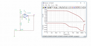
Side note thing again: So R8 and C3 are forming the Low Pass and C11 and R2 are forming the High Pass? even though R2 is then connected to a cap and another resistor?
1.My Three questions are is that R2 essentially there just to form the High pass filter?
2. How do you design the cap for c7 (Pick the value)
3. When this person was designing the low pass filter in the NFB he made the Fc lower than the input LP filter, is he then making the NFB LP filter the dominate pole in his circuit?
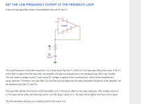

Yes, that's right. The C7 is very low impedance at signal frequencies
and doesn't have much effect on the HP filter
R2 is mainly for a reasonable input impedance for the circuit, Otherwise C7 would short the + amp input to ground at signal frequencies. Also R2 is used as part of the HP filter.
C7 should be much larger than C11, perhaps ten times.
Usually the output blocking capacitor C6 will set the dominant pole, if only for economic reasons.
Last edited:
- Status
- This old topic is closed. If you want to reopen this topic, contact a moderator using the "Report Post" button.
- Home
- Amplifiers
- Chip Amps
- Purpose of a feedback Capacitor (Ci)
