Does it matter which pole you make dominate in terms of either LP's or HP's?
Cause wouldn't naturally the LP have the most dominate pole as its pole is
closer to the "origin" of a root locus? would you then make one of the LP filters
the dominate one? and does it matter which( the input one or the NFB one)?
Some feel that input frequencies outside of the audio band should be prevented
from entering the amplifier, so then the input filter(s) would be made dominant.
The nfb pole should normally be the lowest frequency pole in the amplifier,
except for the poles in the power supply itself.
Last edited:
Some feel that input frequencies outside of the audio band should be prevented
from entering the amplifier, so then the input filter(s) would be made dominant.
The nfb pole should normally be the lowest frequency pole in the amplifier,
except for the poles in the power supply itself.
Yeah that makes sense, just double checked on matlab, higher frequencies cut off has bigger poles thus less dominate. So to pick the cap value for it just anything lower than your dominate LP filter I guess right?
Sorry, so now how would you decide the cap on the output? that blocks DC again that was a little confusing.
Having higher cut off frequencies wouldnt that default make HP filters the dominate pole then?
how would you decide the cap on the output? that blocks DC again that was a little confusing.
Having higher cut off frequencies wouldnt that default make HP filters the dominate pole then?
See post #57 for the output capacitor.
A non-dominant LF pole should be several times (5-10 if possible) lower in frequency
than the dominant system LF pole. The idea is to have the system behave more like a single pole.
Of course, if you want sharp filters for some reason (like a phono LF resonance filter, or
an anti-aliasing filter), that isn't possible.
The amplifier's stability is not directly affected by the open loop input/output filters,
though they could hide some mild amp misbehavior by filtering it out before you could see it.
That would be bad practice to allow.
Last edited:
See post #57 for the output capacitor.
A non-dominant LF pole should be several times (5-10 if possible) lower in frequency
Yup, remember this in control theory.
I think I am starting to get the outcap values, essentially you want the XC to be as low as possible due to affecting your output power as its in series with your output cap right?
so using the relationship p = V^2(R+XC) you want ur XC to be potentially zero across all frequencies right?
Last edited:
you want ur XC to be potentially zero across all frequencies right?
Yes, as much as possible, but it will never be zero. Generally a factor of ten
below the lowest frequency of interest is considered adequate. This assumes
no non-audio input, like phono LF resonance, etc.
Last edited:
Yes, as much as possible, but it will never be zero. Generally a factor of ten below the lowest frequency of interest is considered adequate.
I see that makes sense.
How do one figure out the values of a zobel network and thevin network?
Just a side note thing: I believe you have linked this before A Complete Guide to Design and Build a Hi-Fi LM3886 Amplifier - Circuit Basics and I am sorry for not following it more carefully as this is everything we have been talking about since, I do apologize but you have put things in way more perspective for me.
How do one figure out the values of a zobel network and the vin network?
The mfr data sheet is best for the Zobel, you have to know the amp IC very well.
The input filter frequencies are more a matter of choice. However, the single supply
bias circuit filter capacitor (which serves as an AC ground for the input resistor)
should be large enough to set a frequency much lower than the input HP filter.
Yeah make sense, however in that guide he just uses the HP filter equation :/
I see, so that capacitor (C2) R1 and R2 form a high pass filter right? is because you want the input HP filter be more dominate than the bias one?
so that capacitor (C2) R1 and R2 form a high pass filter right?
is because you want the input HP filter be more dominate than the bias one?
Yes, the single supply bias filter capacitor should have virtually no effect on the input signal.
If it is sized too small, it also can cause a LF boost, depending on the rest of the circuit.
Last edited:
Yes, the single supply bias filter capacitor should have virtually no effect on the input signal.
If it is sized too small, it can cause a LF boost, depending on the rest of the circuit.
Meaning becoming more dominate I see I see, everything slowly coming together.
I was wondering do you know by any chance how he makes an open loop op amp ? LM3886 Chip Amp Stability Analysis I was wondering If I could do the same
how he makes an open loop op amp ?
For simulation. he used an LC filter (set to a very LF) in the nfb loop, to retain DC stability.
For lab measurement, he used an injection transformer and a network analyzer,
which is standard practice.
Last edited:
For simulation. he used an LC filter (set to a very LF) in the nfb loop,
to retain DC stability.
For lab measurement, he used an injection transformer and a network analyzer,
which is standard practice.
I see I see,
I guess we covered pretty much everything should I be okayish now at least and start discover my own traits ?
I guess we covered pretty much everything should I be okayish now
at least and start discover my own traits ?
Good luck.
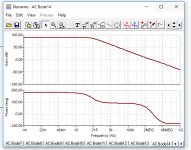
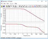
Trying to figure out the PM and GM of the LM1875 open loop.
Looks like a phase shift of near 180 at unity gain, that's bad.
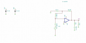
Try an RC Zobel on the output, 1 ohm and 0.22uF.
Tried that already, thinking that you must compensate the phase using the
zobel network as it adds a pole, however it looks the same?
Yes it does, are you sure the RC is implemented right? It should have a
visible effect on the OL gain/phase curves.
- Status
- This old topic is closed. If you want to reopen this topic, contact a moderator using the "Report Post" button.
- Home
- Amplifiers
- Chip Amps
- Purpose of a feedback Capacitor (Ci)


