Yes, first you decide on the response needed. Then you try to achieve that goal
within the amplifier's limitations. The hard part is the amp and related nfb components,
to achieve the desired gain but still be stable at hf.
The input circuit, and output capacitor sizing, are relatively simple.
Agreed.
How about this in the input I want to filter out Radio Frequencies but still limit the frequencies that are wasted, the human hearing is somewhere between 150Hz to 20Khz? Which ever it is I want to limit it there? and this is all at the input right ? or output?
How about this in the input I want to filter out Radio Frequencies
but still limit the frequencies that are wasted, the human hearing is somewhere
between 150Hz to 20Khz? Which ever it is I want to limit it there? and this is all
at the input right ? or output?
Yes, deciding the input bandwidth limitations is one of the key starting points.
This is set by the Rs and Cs in the input circuit block connected to the + amp input.
The output signal is also LF filtered by the output coupling capacitor in this single supply design.
A basic equation used for this is f = 1/(2Pi x R x C)
Last edited:
Yes, deciding the input bandwidth limitations is one of the key starting points.
This is set by the Rs and Cs in the input circuit block connected to the + amp input.
The output signal is also LF filtered by the output coupling capacitor in this single supply design.
A basic equation used for this is f = 1/(2Pi x R x C)
Why not put all the filters in the input instead of putting one at the input and one at the output.
Why not put all the filters in the input instead of putting one at the input and one at the output.
You must use an output coupling capacitor in this circuit because the output DC voltage
is at half the supply, Vcc/2. This is set by the input DC bias network. This is always true
for a single supply amplifier circuit.
When using a dual +Vcc/0V/-Vdd power supply, the output coupling capacitor is not needed.
This is because the amp DC output voltage can be forced to be very close to 0V DC, by using
a large capacitor to connect the nfb network to ground. At DC. the capacitor is an "open circuit"
so the amp becomes a voltage follower. Since the input voltage is 0V DC, and the DC gain
is 1 (0dB), then the output voltage is close to 0V DC.
Last edited:
You must use an output coupling capacitor in this circuit because the output DC voltage
is at half the supply, Vcc/2. This is set by the input DC bias network. This is always true
for a single supply amplifier circuit.
When using a dual +Vcc/0V/-Vdd power supply, the output coupling capacitor is not needed.
This is because the amp DC output voltage can be forced to be very close to 0V DC, by using
a large capacitor to connect the nfb network to ground. At DC. the capacitor is an "open circuit"
so the amp becomes a voltage follower. Since the input voltage is 0V DC, and the DC gain
is 1 (0dB), then the output voltage is close to 0V DC.
Yeah I get the input bias circuitry, what I meant was the bode plot.
Do you consider the bode plot frequencies or do you shove in LP and HP filters till your satisfied

View attachment 682953
This is what I meant, do you design for this or do you just let it be.
At LF you have flexibility, and the amp can go very low if the feedback capacitor is large enough,
and if the input/output coupling capacitors are large enough.
At HF you are limited by the amp's own characteristics. For this circuit, an output RC snubber
to ground (required for stability), along with the amp's own HF behavior, will set the HF response.
Last edited:
I heard this before, but why only at lf? Is it because the low frequencies causes the cone to displace more oppose to Higher frequencies thus having the cone take more energy?At LF you have flexibility, and the amp can go very low if the feedback capacitor is large enough,
So what should I do? Is there still point putting a HP filter ?At HF you are limited by the amp's own characteristics
So how does one goes about designing the frequencies for the op amp.
I want to filter out radio and have it so useless frequencies gets filtered.
Is there still point putting a HP filter ?
So how does one goes about designing the frequencies for the op amp.
I want to filter out radio and have it so useless frequencies gets filtered.
With this single supply circuit, you must have a DC blocking capacitor
at both the input and the output. These are HP filters.
To filter out HF above say 40kHz, use a series R and a shunt C at the input.
Usually the series R is much smaller than the input impedance, perhaps 1k.
Then the shunt capacitor to ground would be 1/ (2Pi x 1k x 40kHz).
This is about 4nF.
This is after the low pass filter right? I see what you mean so the DC blocking cap at the output is dual purpose, one being a a DC decoupler and 2 a High pass filter.
KK I am confused here is a high pass filter forming with C1 and R1 or C1 and R2 or is it C1 R1//R2 ?
This is after the low pass filter right? I see what you mean so the DC blocking cap at the output is dual purpose, one being a a DC decoupler and 2 a High pass filter.
I am confused here is a high pass filter forming with C1 and R1 or C1 and R2 or is it C1 R1//R2 ?
The input HP filter can be before , after, or combined with, the input coupling HP filter capacitor..
The input network is a little more complex than a simple RC single pole high pass filter,
but that is its main function.
Last edited:
The input HP filter can be before , after, or combined with, the input C coupling HP capacitor..
The input network is a little more complex than a simple RC single pole high pass filter.
Agreed, another question whats the point of having filters at the output if they are being filter at the input.
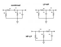
If the input network is complicated for filters how does one design it? I have seen tutorials where they shove just a high pass filter and a low pass and be done with it.
If the input network is complicated for filters how does one design it? I have seen tutorials where they shove just a high pass filter and a low pass and be done with it.
Here are three possible input RC filter circuits (omitting the single supply biasing network).
Attachments
Last edited:
I see I see, that makes sense.
So essentially to make your op-amp bandwidth you just shove filters essentially in.
Dont have to worry about the poles or zeroes?
Why is the point of the output filter as the frequencies are already getting filtered in the input.
Filters have poles and/or zeros, just not those in the amplifier IC or nfb network.
The output coupling capacitor blocks DC from the speaker in a single supply amp.
The output RC Zobel to ground is required for stability for this amp IC.
Yup yup makes sense,
I meant as the Output coupling capacitor in series with the speaker creates a high pass filter no?
so I guess might as well design for it? How do you pick your value of C7, the Cap in NFB
The impedance of the output coupling capacitor should be small compared to the speaker impedance.
If the speaker is 8 ohms, and "small" is a factor of ten at 20Hz, then C = 1/(2Pi x (8ohms/10) x 20Hz) = 10,000uF.
For the nfb cpacitor to ground, if you want it to rolloff at 2Hz, and the nfb has 100k and 10k resistors,
then C = 1/(2PI x 1k ohm x 2Hz) = 159uF.
\
If the speaker is 8 ohms, and "small" is a factor of ten at 20Hz, then C = 1/(2Pi x (8ohms/10) x 20Hz) = 10,000uF.
Why 20HZ? if I may ask :/
Sorry, I guess I am not that smart as you, but why 2HZ? I get that its just a arbitrary term, however dont you already have Low pass filters in your input to depict the roll off at the low frequencies?For the nfb capacitor to ground, if you want it to rolloff at 2Hz
Why 20HZ? if I may ask :/ why 2HZ? I get that its just a arbitrary term, however dont you
already have Low pass filters in your input to depict the roll off at the low frequencies?
Just an example for the output coupling capacitor, it could be whatever LF rolloff you want.
Many companies would want to minimize the uF value to reduce the parts cost.
In a system with several low frequency poles, it's best to stagger them
by making one particular LF pole dominant (higher in frequency than the other poles).
The output coupling capacitor is the most expensive part, so it should set the
dominant pole and have a small uF value.
The 2Hz nfb HP capacitor is a decade below the output HP capacitor for that reason,
and also its distortion is lowered by reducing the AC signal voltage across it when it is larger.
A small capacitor like that is much cheaper than the output coupling capacitor,
so it should set a lower LF pole for cost reasons as well.
Last edited:
I see I see
Does it matter which pole you make dominate in terms of either LP's or HP's? Cause wouldn't naturally the LP have the most dominate pole as its pole is closer to the "origin" of a root locus?
oh I see, would you then make one of the LP filters the dominate one? and does it matter which( the input one or the NFB one)?
Last edited:
- Status
- This old topic is closed. If you want to reopen this topic, contact a moderator using the "Report Post" button.
- Home
- Amplifiers
- Chip Amps
- Purpose of a feedback Capacitor (Ci)