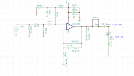
yea you're right.Otherwise C7 would short the + input to ground.
C7 should be much larger than C11, perhaps ten times.
Ill just trust you on that.
Usually the output blocking capacitor C6 will set the dominant pole,
Is C6 not a High pass filter? I thought you mention that your LP filter at the input is what you want your dominate pole to be at?
Last edited:
Is C6 not a High pass filter? I thought you mention that your LP filter
at the input will be the dominate pole?
There are dominant poles at each end of the frequency range.
C6 will usually set the dominant LF pole. C3 will usually set the dominant HF pole.
However, neither of these directly affects the stability of the amp.
Only the nfb and snubber components do.
Last edited:
Whats the point of having a dominate pole at the high frequencies? Wouldnt the system follow the behavior which ever pole is at low frequency?There are dominant poles at each end of the frequency range.
C6 will usually set the dominant LF pole. C3 will usually set the dominant HF pole
Sorry but isnt C6 a high pass filter with the speaker? As frequencies poles go down so does your pole location, however I am pretty sure High pass filters have a high cut off frequency thus high pole location? Wouldnt it make more sense for a LP filter be the dominate LF pole?
Only the nfb and snubber components do
Isnt that why you want your low pass filter in the NFB circuit to be the dominate LP pole as your OP amp will now behave as a first order system?
Whats the point of having a dominate pole at the high frequencies? Wouldnt the system follow the behavior which ever pole is at low frequency?
Sorry but isnt C6 a high pass filter with the speaker? As frequencies poles go down so does your pole location, however I am pretty sure High pass filters have a high cut off frequency thus high pole location? Wouldnt it make more sense for a LP filter be the dominate LF pole?
In a feedback amplifier, usually a single dominant HF pole is necessary for HF stability, though
there are other methods as well. In a wide bandwidth system, the behaviors at LF and HF
are more or less independent. The dominant LF pole is the one at the highest frequency
below the midband region.The dominant HF pole is the one at the lowest frequency above
the midband region.
Normally an added bandwidth limiting input filter will set the HF and LF dominant poles,
but perhaps not necessarily in the case of an amp using an output coupling capacitor.
Last edited:
In a wide bandwidth system, the behaviors at LF and HF are usually independent.
The dominant LF pole is the one at the highest frequency.
The dominant HF pole is the one at the lowest frequency.
Hold on, Really? For example
Maybe I am not smart enough as you, but here
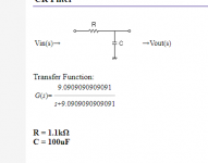
LOW pass filter
Pole location = -9.0909
HIGH pass filter
Pole location = -100000000
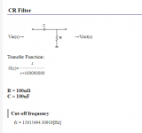
Isnt the Low pass filter < High pass filter poles
I am pretty sure as you have lower frequencies so is your pole locations.
There are two groups of system poles, LF and HF.
Of all the LF poles, the dominant one is at the highest frequency of the LF group.
Of all the HF poles, the dominant one is at the lowest frequency of the HF group.
This assumes the poles in the group are not close together.
Of all the LF poles, the dominant one is at the highest frequency of the LF group.
Of all the HF poles, the dominant one is at the lowest frequency of the HF group.
This assumes the poles in the group are not close together.
Last edited:
...Maybe I am not smart enough as you...
I think you have plenty of smarts.
What Rayma has more than you is *experience*. He's been through all this. You can get there too, in time.
But instead of using your smarts to think-though your questions, you are firing-off questions every 4 minutes. Rayma has been quite accommodating, yes. But you would Learn More by writing out your question, and then trying to answer it *yourself*, rather than ask others to go into every detail.
Isnt that why you want your low pass filter in the NFB circuit to be the
dominate LP pole as your OP amp will now behave as a first order system?
I would want C2 to set a rolloff of about 2Hz, well below audio frequencies.
Ideally C11 would be the dominant LF pole, but in practice C6 probably will,
due to size/cost reasons.
I would want C2 to set a rolloff of about 2Hz, well below audio frequencies.
Ideally C11 would be the dominant LF pole, but in practice C6 probably will,
due to size/cost reasons.
Hey, I am sorry but can you explain the dominate Pole compensation?
Here is what I get:
It's just High pass and low pass filters, due to adding a pole and zero thus a compensation in the network
Here is what I was taught in class:
This is all in respective to a root locus.
-------------------------------------------
Transfer Function 1:

Bode TF1:
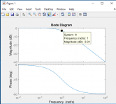
Rlocus TF1:
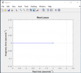
Pole = - 1
Fc = 1
--------------------------------------------
Transfer Function 1:
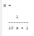
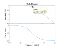
Bode TF1:
Rlocus TF1:
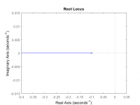
Pole = - 0.1
Fc = 0.1
-----------------------------------------
Together:
Pole1 = -0.1
Pole2 = -1
Fc ~ = 0.0988
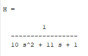
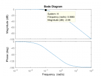
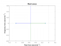
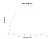
The point I am trying to make is, as you can see even though its a second order system it still behaves as a first order (in the step response shown) due to the poles being x10 away, thus imitating the pole closet to the 0 (shown in the root locus).
Another relationship I want to show is as cut off frequency decreases so does pole location and what is shown above the system should behave closest to the pole with the lowest Cut off frequency in this case when the pole = -0.1
Sorry If I am getting confused about grouping HF and LF etc etc, but if you can explain in these lament terms I think I would get it.
My theory is this, in control theory or not even that in any system you want a first order system because its the easiest in terms of predicting and what not, in an op amp when inserting HP or LP filters (compensation) you have a choice of predicting it's system order by making one of the filters dominate.
TO me what makes sense is making the Low pass filter in the NFB the dominate pole due to being in the feedback, just a guess. And in order to make this dominate the pole of this filter should be at the lowest cut of frequency compare to the other low pass filter at your input.
- Status
- This old topic is closed. If you want to reopen this topic, contact a moderator using the "Report Post" button.
- Home
- Amplifiers
- Chip Amps
- Purpose of a feedback Capacitor (Ci)
