Had a day off the fourm seems like I missed allot, I had a quick read through your guys comments.
I read back and I have to say, I had read tube amp circuits and some nelson pass circuits too. But the main inspiration wasn't from those.
The main inspiration for the pre amp circuit se on high voltage is from my transistor headphone amplifier, utilizaing a similar gain stage then cap couppled to a ocl output stage. It worked extremly well, so I decided to see what would happen if I made a pre amp circuit on a similar topnology.
I come to think you mentioned in an earlier post you were using your circuit in a SE configuration, in combination with high voltage and cap coupled gain stages it looks like an inspiration from tube amplifier circuits, is it? You may have already come across Nelson Pass circuits one will notice many of his simple circuits have an apparent similarity with tube circuits too.
Regarding your original question I don't have so much to add though a bit of voltage headroom makes gain stages become a bit more linear, except that high voltage circuits requires transistors which can withstand a higher voltage, but with higher voltage the current may need to be decreased in order to not exceed a given power dissipation limit, also there are a few fine audio transistors which doesn't exist in high voltage configurations, so there are both pros and cons.
Anyhow, I think what you are doing is a path worth to explore.
I read back and I have to say, I had read tube amp circuits and some nelson pass circuits too. But the main inspiration wasn't from those.
The main inspiration for the pre amp circuit se on high voltage is from my transistor headphone amplifier, utilizaing a similar gain stage then cap couppled to a ocl output stage. It worked extremly well, so I decided to see what would happen if I made a pre amp circuit on a similar topnology.
Last edited:
You fitted the characteristics of a non-feedback device into the feedback equation...This does not prove that a resistor is a feedback device. It merely shows that the theory of feedback can be properly applied to circuits which are not usually considered to use feedback.
This is the crux. You seem to be claiming that if you can model a potentiometer using the NFB equation that it is legitimate to consider a potentiometer to be a NFB device.Your argument seems to be that as an emitter follower can be modelled as a potential divider (although only at low frequencies) then it must be modelled as a potential divider and cannot involve feedback. But that same argument shows that a potential divider (which can be modelled using feedback theory) must be a feedback system. In a sense it is, as the current through R1 is modified and reduced by the voltage developed across R2.
So we have to agree that an emitter follower (at low frequencies) and a potential divider are both feedback systems and Ohm's Law systems. As always in science, you use the model which best fits and gives the easiest sums.

No it isn't. Not by the commonly accepted definition of a feedback system.Now, as I said, the non-inverting opamp buffer is the same circuit as an emitter follower. By your logic the non-inverting opamp is not a feedback system. At high frequencies the potential divider model for an emitter follower breaks down, but the feedback model still gives the right results. The active device sees only the difference between the input signal and the output signal: that is feedback.
It is generally true in audio that when someone claims "no feedback" the truth of the matter is that massive feedback is used, but he wishes to impress those who are opposed to feedback and don't understand it. Using a term to mean the opposite of its correct meaning cannot be lightly dismissed as being merely "colloquial"; those who point this out.Ultima Thule said:I would still like to maintain what I earlier said, the colloquial use of "no feedback" amplifiers are still valid and widely understood, and it is not meant to be confused with academic textbook examples wherein for example the intrinsic feedback mechanisms in BJT's is discussed, which I have never opposed to and understand very will its use and value.
I have seen even Mr. Pass colloquially using "no feedback" when describing circuits in the context of audio amplifiers.
Rule 1: when losing a technical argument, accuse the other side of autismWhat I am asking above is not the answer, but where do we draw the boundaries in such discussion regarding "feedbacks" and "loops", think of a Mandelbrot, we dive deeper into it and the pattern repeats over and over again, down to an atomic level, and who knows maybe there are even smaller bits and pieces well beyond the atoms which provides for the possibility to maintain feedback actions, eg. we reach to a new bottom of "academic Asperger, drivel and nonsense" when peoples vocabulary is exempt of the word "colloquial" and start nitpicking and going on a n/\zi barrage because of some people are using the "non feedback" term to explain their audio amplifier circuit for an intrigued public, talk about party pooper.
Rule 2: quote a 'guru' who makes the same mistake as you do
Rule 3: having lost a technical argument, just say you were being "colloquial"
I am using your argument, which appears to be that as an emitter follower can be modelled using something other than feedback then it cannot use feedback. I am simply demonstrating where your argument leads. You want to claim that a potential divider just uses Ohm's Law and an emitter follower just uses Ohm's Law so no feedback is involved in either of them. I have shown that both can be modelled using the idea of feedback, which some might (wrongly) conclude as meaning that neither of them employ Ohm's Law.traderbam said:This is the crux. You seem to be claiming that if you can model a potentiometer using the NFB equation that it is legitimate to consider a potentiometer to be a NFB device.
Perhaps it might help if I said that Ohm's Law (etc.) is circuit theory, and feedback is a first level abstraction which can be applied to all sorts of systems (including potential dividers, emitter followers and opamps). The more complex the system, the more light you get from using an appropriate abstraction.
I think you will find that all the texbook writers regard the emitter follower as a feedback system. If the EF is not a feedback system than an opamp is not a feedback system either. The fact that a BJT has a shared pin for input and output and typically an opamp does not is a mere detail; if someone made an opamp with the -ve input and output sharing a pin would you say that as a result of this it no longer employs feedback?
@DF96
I'll give you credit for completely surprising me. I never thought anyone would suggest a resistor is a feedback system. I can easily show an emitter follower is equivalent to a resistor network without feedback so I thought I had clinched this argument.
But no! You've come out of left field by coming up with an entirely new definition of feedback itself and, by implication, what the electrical definition of a resistor is.
I have to concede. I just can't compete at that level of craftiness.
This was a joke.A resistor is a 100% feedback device because it cleverly adjusts I to be V/ R.
It is clear to me that an emitter follower is a negative feedback circuit exactly as a buffer using an op-amp wired in the non inverting mode at Av=+1.
In both cases the output follows the input thanks to an active device receiving 100% feedback.
IMA(rogant)O. All the rest is word distortion and idle talk.
Consider a CFP. Here you do see the 100% feed back loop and the two transistors actually make a one transistor emitter follower
Last edited:
@DF96
aaw... those pesky cheap shots when runing out of objective arguments...
Now, go look up all written media since the dawn of humanity containing the term "open loop" and all its variants such as "open loop gain" etc and persecute those people with your academic technocrap bullying.
feedback = closed loop, right?
The fact that a BJT has a shared pin for input and output and typically an opamp does not is a mere detail; if someone made an opamp with the -ve input and output sharing a pin would you say that as a result of this it no longer employs feedback?
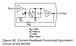
I believe you can buy a closed loop buffer chip that is just an opamp with the output internally connected to the inverting input.
It is also used inside instrumentation opamps.
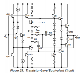
Edit: found a couple. The BUF604 is interesting because it is internally a CFA with the output hard wired to the inverting input. How's that for controversy - a single post heresy on emitter followers AND CFAs. 100% feedback and it is all invisible!
Jan
Attachments
Last edited:
When you start to follow that train of thought, all kinds of interesting circuits pop up.
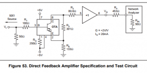
Most here are probably familiar with the so-called 'ideal transistor' or 'CCII' or 'diamond transistor' or whatever marketing came up with, like the OPA860.
Illustrates nicely the familiar resistive feedback divider feeding back to the emitter which functions as inverting input.
Jan
Most here are probably familiar with the so-called 'ideal transistor' or 'CCII' or 'diamond transistor' or whatever marketing came up with, like the OPA860.
Illustrates nicely the familiar resistive feedback divider feeding back to the emitter which functions as inverting input.
Jan
Attachments
That, Sir, is your privilege, and you are fully entitled to it..... I am unable, at the moment, to understand .....
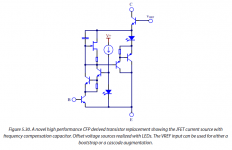
Consider a CFP. Here you do see the 100% feed back loop and the two transistors actually make a one transistor emitter follower
Another nice example!
Edit: here's a super duper 'emitter follower' from Arto Kolinummi's book.
Linear Audio | your tech audio resource
Jan
Attachments
Last edited:
A bunch of resistors can make a routing calculator.
Believe it or not, I have seen this used in a transmission network. They were modeling the network with an image resistor network. Resistor values as weights of link capacities. When applying a voltage at two nodes, the currents in the net, instantly was giving the best route.
As you can see resistors are not only clever feed back devices ( a joke ) but ultra fast calculators ( hard to believe but true ) .
Isn't mind boggling ?
Kirshof and ohm laws solving at the speed of light a bunch of simultaneous equations as large as you wish...
Last edited:
I know. But if you believed that an emitter follower was equivalent to a few resistors in parallel then your next statement would make it no jokeThis was a joke.
...It is clear to me that an emitter follower is a negative feedback circuit exactly as a buffer using an op-amp wired in the non inverting mode at Av=+1.
Sure. There is a loop and excess gain. The % may vary.Consider a CFP. Here you do see the 100% feed back loop and the two transistors actually make a one transistor emitter follower
What I have learned working on looped systems is you cannot inside the loop think in terms of causes and effects as you would on a open loop system.
On a open loop system you can start from the input to say, this causes this effect and progress further this way to the output.
On a looped system you cannot start from some point in the loop and progress around it, imagining causes and effects. This can give a right conclusion as well as a wrong one. Actually it gives invalidated results. There is no well identified causes that give effects in a loop, all is intricated by simultaneous relationships that are instantly solved in the loop.
Intuition is misleading on looped systems, I only trust right modeling and right equation solving.
Intuition can give good ideas and brillant explanations, but is nothing if not backed by physics mathematics and system theory.
This is my 2 cents.
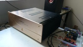
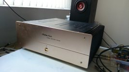
The main reason keeping me away from the L channel is that I did not realised I had 2 extra 24v supplies in my house untill I found out.
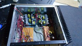
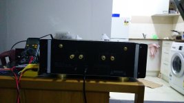
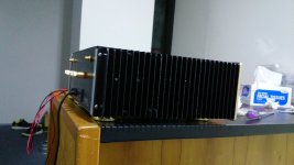
I installed my other channel and stuff is geting a cooking hot inclduing the switch mode inside. Drilled holes to increace natrual flow to the switch mode power supply.
I also did a minor mod to both channels, small mod but big diffrence in sound quality, sounds like a whole diffrent amp after the small mod.
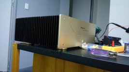
Also swapped out the sanken transisors for tip3055 2955. I used sanken because I had 6 pairs of them. But after a direct comparison with l and r channel. Sankens soundled like a whole other amp with very poor resolution in midrange.
TIP3055s kept me away cause I only had 3 pairs of mospec and another 3pairs of st microelcotirc, did not want to use diffrent brands on l and r channel but ended up doing this cause I did not want to use my new 10 pairs of tip35c. (6pairs per channel of 36c 35c for next project class a)
TIP3055s sound perfect through all frequencies. Much more tube like taste and smooth golden warm midrange, I have tip35c 36c but those are for my next project with increaced cooling and +-24v to +-36v. Also with extra transistors in voltage gain stage to boost sound quality, if my new schematic dreamed of will operate.
I never had thought japanese transistors sounded that bad.
I knew from my exprience just changing out all japanese transistors to non japnaese transistors sounded better, but did not realised how big this impact was untill I had a direct comparison.
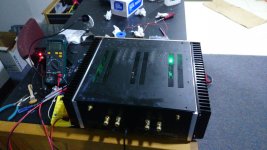
EDIT: with the from pannel instealled everything has heat sink paste in contact, so the heat sink in contact with the case also transfers heat. The front pannel also is very hot hand boling ,little less hot than heat sink but hot.
Bias current stays the same about 2.5amps but temps droped about 3C
I installed my other channel and stuff is geting a cooking hot inclduing the switch mode inside. Drilled holes to increace natrual flow to the switch mode power supply.
I also did a minor mod to both channels, small mod but big diffrence in sound quality, sounds like a whole diffrent amp after the small mod.
Also swapped out the sanken transisors for tip3055 2955. I used sanken because I had 6 pairs of them. But after a direct comparison with l and r channel. Sankens soundled like a whole other amp with very poor resolution in midrange.
TIP3055s kept me away cause I only had 3 pairs of mospec and another 3pairs of st microelcotirc, did not want to use diffrent brands on l and r channel but ended up doing this cause I did not want to use my new 10 pairs of tip35c. (6pairs per channel of 36c 35c for next project class a)
TIP3055s sound perfect through all frequencies. Much more tube like taste and smooth golden warm midrange, I have tip35c 36c but those are for my next project with increaced cooling and +-24v to +-36v. Also with extra transistors in voltage gain stage to boost sound quality, if my new schematic dreamed of will operate.
I never had thought japanese transistors sounded that bad.
I knew from my exprience just changing out all japanese transistors to non japnaese transistors sounded better, but did not realised how big this impact was untill I had a direct comparison.
EDIT: with the from pannel instealled everything has heat sink paste in contact, so the heat sink in contact with the case also transfers heat. The front pannel also is very hot hand boling ,little less hot than heat sink but hot.
Bias current stays the same about 2.5amps but temps droped about 3C
Attachments
-
 DJ41diQVoAIm3is.jpg98.2 KB · Views: 260
 -
 DJ6M7BaVAAEuCKk.jpg181.9 KB · Views: 254
 -
 DJ6jQVtUEAAPZoY.jpg140.7 KB · Views: 154
 -
 DJ6jL6jVYAAQc9c.jpg104 KB · Views: 494
 -
 DJ6jK_SUMAADX9O.jpg108.1 KB · Views: 520
 -
 DJ6jI77VYAIx1mT.jpg122.6 KB · Views: 522
 -
 DJ6jGe8V4AESXX6.jpg145.3 KB · Views: 534
 -
 DJ5dimTVwAA_lPM.jpg47.8 KB · Views: 543
 -
 DJ5djhPV4AAQAZC.jpg84.3 KB · Views: 170
Last edited:
My amd gpu x128 heat sink runs at 80+C and ran well for more than 5 years. It actually still works today but is too slow, outdated.Hi Mrcloc,
Yes, I got where he was coming from.
It's important to remember that the heat sink temperature is Ta, the ambient temperature, and the case temperature is higher than that. The die temperature will of course be even higher, and this is the temperature that matters. So a larger heat sink will not allow you to run it any hotter at all. It will lower the temperature if the total heat dissipation of the transistors remain the same. Yes, you can spread the dissipation out across more transistors. This will increase the SOA of the output stage.
The increase in sound quality is due to the idle current and not the temperature. This is especially true for Mosfet devices, but I find BJT transistors more linear than Mosfets are. The advantage with a Mosfet is that their SOA curves are higher than a similarly rated BJT. That and the amount of energy required to drive a Mosfet is often lower than a BJT, but they still need power to drive the gate charge. That means you need something better than a stage made from TO-92 devices to drive them properly.
The main point I'm trying to illustrate is something you said as well. Cooler devices will last much longer, and temperature is not the thing that allows a transistor to be more linear. That depends on current levels. A larger heat sink helps to lower the temperature at the same power levels.
Best, Chris
I'd assume transistors used in amplifiers to have equivlant or better heat tolerances.
I had ran to-92 transistors with bias boost and calculated internal temp was about 100-110c. max temp is 150c. It was heat sinked and ran at about 480mW. It ran for more than 3 monts still going untill I modded my amp again.
For my 3 pairs class ab vs 7 pairs output class ab. Both situations idle current was kept excatly the same. Had actually measured the idle current. I went from 3 to 5 pairs, then went from6 to 7.
Can hear a big diffrence when going from 5to 6 pairs, still a diffrence from 6 to 7 pairs but less noticble
Last edited:
- Status
- This old topic is closed. If you want to reopen this topic, contact a moderator using the "Report Post" button.
- Home
- Amplifiers
- Solid State
- PROS? High Voltage VS Low Voltage Amp