I view the decreased distortion as negible same amp class ab just higher voltage.I believe that for a given circuit, higher supply voltage generally produces lower distortion, which is borne out in both simulation and real-amp measurement. Sometimes it depends on the circuit how much improvement will be gained with the increased supply, but it is generally an inexpensive and simple way to improve performance.
Higher voltages means you bias current will be less, and class a power output is dependant on current only, ignoring the fact that you need enough supply voltage for your amp to have enough voltage swing.
I designed a +-7.5v ocl head amp, can drive speakers with pre amp. Sound quality wise very similia to my power amp and have same or better sound.
I am still 100% on my point, emitter degenration dosen't have any looping feedback where any output is feed back into any input.
It dosen't sense the current of the output and somehow like magic feed voltage of output back into any inputs to nfb.
First accept that the fact common emitter is simila to a common collector, whatever waveform is feed into base, you see approx 90-100% of that voltage at emitter, the waveform causes emitter voltage to change and this changes the voltage accross emitter resistor, this forces the collector and emitter current to change.
Similary common emitter with degenration, you have a collector resistor, when voltage at emitter changes, this forces the current to change. Causing a voltage swing at collector, becasue the collector resistor is in series with the transistor, the current through collector resistor is also forced to change, and you cannot escape from ohms law thefore it causes a voltage swing at collector.
Common emitter without feedback means emitter is directly grounded, now all the voltage seen at base is dropped through internal resistance (Rpi), rpi changes according to formula 25mV/Emitter Current. Obviously one can see emitter current will change causing a change in rpi, this means the transistor gain will largly change.
Whereas with degeneartion, the emitter resistance is many times bigger typically more than 100 times bigger than rpi, therfore when a sine occurs, the change in rpi causing a change in gain porptional to voltage input becomes negible.
EDIT: If all output is beeing feedback into input, then that means the the ammount of feedback occuring is inifinity, which means the output should have aboslutley zero distortion. In real world this dosen't happen.Not sure what your point is or whoever you are addressing, but I don't think you can tie the concept of feedback to a single component. Feedback is in my view a circuit property.
For instance, the 100% feedback of an emitter follower we discussed before is taught to students at Georgia Tech as the attached.
Jan
If you say omitt the emitter resistance of emitter follower? All that happens is that voltage seen at emitter stays same as before, but now the current through transistor changes according to rpi, the current vs output now is no longer a normal graph y=x type of thing. It becomes some sort of exponential function.
If they say all of the output is feedback into base, I would want to see some detalid explantation along with a professional drawing of the hybrid pi model for it. Clearly they do not have any of this.
Last edited:
Well I won't recommend anyone to study at Georgia Tech if this is their standard.Not sure what your point is or whoever you are addressing, but I don't think you can tie the concept of feedback to a single component. Feedback is in my view a circuit property.
For instance, the 100% feedback of an emitter follower we discussed before is taught to students at Georgia Tech as the attached.
Jan
The equations shown are not a proof. More of a lazy sleight of hand.
For NFB you start with the equation that closed loop gain = A / ( 1 + AB ) where A is the forward path gain and B is the feedback path gain.
Now try determining A and B for the emitter follower.
Meaningless statement.traderbam said:Does a resistor use 100% NFB?
Resistors form most of the feedback elements in most circuits.When people are talking about using NFB in a circuit they aren't really talking about resistors.
If you live in a free country then you are entitled to redefine "feedback" to mean whatever you wish, but this may hamper discussion with others. You are not entitled to redefine the laws of mathematics and physics so that something which everyone else calls feedback (because that is what it is) somehow magically ceases to be what everyone else calls feedback and loses all the properties of feedback.Ultima Thule said:Regarding the expression "feedback/NFB" I understand what you mean so no problem for me, from a casual daily speech point of view at least I use to see the use of the word/abbreviation "feedback/NFB" in the context of a "circuit level" discussion, that opposed to "component level", meaning that the feedback path is taking an external way around the active component encompassing more than one node, the rest while correct is just academic Aspberger, drivel and nonsense.
It senses a good proxy for the current at the output. You seem to be under the false impression that feedback only senses voltage.SMY14INCH said:I am still 100% on my point, emitter degenration dosen't have any looping feedback where any output is feed back into any input.
It dosen't sense the current of the output and somehow like magic feed voltage of output back into any inputs to nfb.
No, because to get zero distortion you would need infinite loop gain. Have you ever looked at the feedback equation? Studying it might help you understand emitter followers.EDIT: If all output is beeing feedback into input, then that means the the ammount of feedback occuring is inifinity, which means the output should have aboslutley zero distortion. In real world this dosen't happen.
The feedback goes to the emitter. This is an input for a BJT. To understand it all you need to do is find and read a good textbook.If they say all of the output is feedback into base, I would want to see some detalid explantation along with a professional drawing of the hybrid pi model for it. Clearly they do not have any of this.
A = Re/re, where Re is the external emitter resistor and re is the internal intrinsic emitter 'resistor', (this ignores Early effect, which is usually small)traderbam said:For NFB you start with the equation that closed loop gain = A / ( 1 + AB ) where A is the forward path gain and B is the feedback path gain.
Now try determining A and B for the emitter follower.
B = 1
Hence close loop gain = (Re/re) /( 1 + Re/re) = Re/(re+Re) ~= 1 - re/Re
Now you are just trolling.SMY14INCH said:One more point on the common collector, both in and outputs are in phase, if anything goes back into input, dosen't this mean you have postivive feedback where gain increacses?
I am still 100% on my point, emitter degenration doesn't have any looping feedback where any output is feed back into any input. <snip>
Actually if you return all of the output to the input there's nothing infinite about it, it is just 100%. Like 100% is 'all of it'? And of course that happens in reality.
It is similar as in an opamp used as a buffer, where the output is connected back to the inverting input. 100% feedback, and just as in an emitter follower, gain tends to unity. It is not into he base, of course, so you won't see that anywhere!
I agree it is not very intuitive if you are new in this area, and it can look strange. But t may be clearer when you take a black box that contains either an opamp or an emitter follower. Connect the B and E to the inputs as non-inverting and inverting input respectively, also connect the E to the output. Then connecting the output to the inverting input in either case is equivalent. In both cases, you get the advantages of feedback: high input impedance, low output impedance, gain close to one, increased bandwidth and decreased distortion.
It is also clear when you use the hybrid pi model you mentioned; just consider the E as both the inverting input and output (exactly as a unity gain opamp buffer with output connected to inverting input). Try to think conceptually.
Here is another explanation, better than I can: Emitter Follower
Jan
Last edited:
One more point on the common collector, both in and outputs are in phase, if anything goes back into input, dosen't this mean you have postivive feedback where gain increacses?
No that is not the case. The B is the non-inverting input, and the E is the inverting input.
It is easy to see that the effective input signal to the emitter follower is Vb - Ve.
So in a practical case (just for AC for the sake of discussion) you send 1V signal into the B, the emitter current increases until you have *almost* 1V at the E. So your gain gets close to 1, since the E is also the output.
The output signal (at E) is fed back to the inverting input (here also E; remember effective input signal is Vb - Ve), so clearly 100% negative feedback.
Again, compare to a unity gain opamp with the output hard wired to the inverting input. Just like an E-follower.
Jan
I think you guys better talk to designers who claim zero nfb, seen the schematics and there are clearly outputs feed back into inputs.
That's OK. I like explaining things to newbee's. There's always some who actually read the posts and Get It.
")
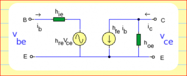
BTW the attached model shows what is meant with E is both input and output (as the opamp buffer example). Just hang an Re between E and gound and hang the C to a power supply, and voilá!
Jan
Attachments
Last edited:
Maybe my point wasn't made clear, I was only talking about feed back where output was connected back to input of any stages to reduce gain.
Emitter degenration has no outputs connected back to inputs. This is going to be the last post I make on this. I am not conviced on your guys comments on changing my thoughts.
Not talking about feedback as where you change something and the gain changes.
Emitter degenration has no outputs connected back to inputs. This is going to be the last post I make on this. I am not conviced on your guys comments on changing my thoughts.
Not talking about feedback as where you change something and the gain changes.
We are talking to such a person in this very thread: someone who claimed 'no feedback, local or global' for a circuit which included emitter followers and emitter denegeration!SMY14INCH said:I think you guys better talk to designers who claim zero nfb, seen the schematics and there are clearly outputs feed back into inputs.
As I keep saying, 'output' includes current. 'Output' can also include good proxies for output.Maybe my point wasn't made clear, I was only talking about feed back where output was connected back to input of any stages to reduce gain.
A good proxy for the output current develops a voltage which is fed back to the input. Note that 'feedback' does not require that the feedback signal be applied to the same input connection as the signal input, otherwise the non-inverting opamp configuration would not be feedback.Emitter degenration has no outputs connected back to inputs. This is going to be the last post I make on this. I am not conviced on your guys comments on changing my thoughts.
You clearly are not convinced. You need to do some more reading and more thinking.
Change the emitter resistor in an emitter follower and the gain changes, exactly according to the feedback equation. See my post 45.Not talking about feedback as where you change something and the gain changes.
Maybe my point wasn't made clear, I was only talking about feed back where output was connected back to input of any stages to reduce gain.
Emitter degenration has no outputs connected back to inputs. This is going to be the last post I make on this. I am not conviced on your guys comments on changing my thoughts.
Not talking about feedback as where you change something and the gain changes.
Well if you were talking about global feedback around a circuit with multiple stages, why didn't you say so? You kept coming back to an emitter follower.
If your point was: 'there is no global feedback around multiple stages in an emitter follower', well duh!
Edit: re: convincing. I know the feeling. One of the hardest things to do, even keeps me awake sometimes.
A method that works for me to sort such things out is take a mental distance, and ask yourself: does it make sense? Up to you of course, but if you never change your mind, you're never getting any smarter than you are now.
. Although, from your reasoning, you're doing pretty good in that department, I grand you that.Jan
Last edited:
I'm sorry, this contains all the best of what I learn in 3 years of amp modding from zero exprience to pro. I am also planning to sell amps and head amps biased arround these schematics.

When asked to show his schematics, SMY posted this statement in another Thread
Post your Solid State pics here.I'm sorry, this contains all the best of what I learn in 3 years of amp modding from zero exprience to pro. I am also planning to sell amps and head amps biased arround these schematics.
No doubt Diyaudio is used as a showwindow by all sorts of merchants.When asked to show his schematics, SMY posted this statement in another Thread
Post your Solid State pics here.
I don't understand.A = Re/re, where Re is the external emitter resistor and re is the internal intrinsic emitter 'resistor', (this ignores Early effect, which is usually small)
B = 1
Hence close loop gain = (Re/re) /( 1 + Re/re) = Re/(re+Re) ~= 1 - re/Re
If you are choosing A = Re/re then are you defining Vin = Vbe and Vout = V(Re)?
If so, I don't get how that can work as an equation for A as these two voltages are not referenced to a common point.
Also, how did you determine that B=1?
B=1 is the easy part: the output voltage is applied without any attenuation in series with the input.
A=Re/re is a little harder to grasp. The amplifier is a BJT, so gain is simply transconductance (1/re) multiplied by output load resistance (Re). The input and output voltages are both referenced to ground before feedback is applied. The snag with the emitter follower is that it is not possible to break the feedback loop as the emitter is both an input and output. However, conceptually we can split these two roles and see that the transistor (like all feedback amplifiers) amplifies the difference between the input signal and the feedback signal.
A=Re/re is a little harder to grasp. The amplifier is a BJT, so gain is simply transconductance (1/re) multiplied by output load resistance (Re). The input and output voltages are both referenced to ground before feedback is applied. The snag with the emitter follower is that it is not possible to break the feedback loop as the emitter is both an input and output. However, conceptually we can split these two roles and see that the transistor (like all feedback amplifiers) amplifies the difference between the input signal and the feedback signal.
It seems that Mr. SMY joins the long list of people trying (and in some cases succeeding) to make a living from audio electronics while having significant gaps in his grasp of audio electronics. Until I arrived on this forum I never realised just how common this is; I naively assumed that people were reasonably competent at whatever they chose as their occupation, including electronics.
- Status
- This old topic is closed. If you want to reopen this topic, contact a moderator using the "Report Post" button.
- Home
- Amplifiers
- Solid State
- PROS? High Voltage VS Low Voltage Amp