Just a quick review on the bass part of my class A amp, it was absolutely beautifull when paired with a 15inch speaker, during bass test the house boomed up. body and funiture was resonating and shaking.
The TV also managed to shake left and right allot which sits right on top of the speaker. I'd say the tv would have fell over if I turned it up even more.
Compared to mid high range amps like ma9s2 clone kit which i have, my class a amp has smooth, realistic and warm mid range. The are also slightly more highs with my amp .
Compared to a all tube amp which I own, the mid range on my class A transistor 50w has less distrotion and overrall is more sweet and soft.
I didn't say it is not Class A. I said it is not "super class A"; no change in idle current is a sign of Class A. I don't know what "super class a" is, but I suspect it is just marketing talk.SMY14INCH said:explain why it is not Class A.
That is Class A: quiescent current equal to peak signal current. Any smaller quiescent current would not be Class A. Any greater quiescent current means you have not reached clipping.What I was implying with the idle current is that it dosen't need to increace right up to near clipping, for a 40v pk-pk the current through transistors required are about 2.5amps, i'm idling somewhere at 2.5amps.
You have clearly drunk deeply from the audiophile myth well.I want to say caps do nothing but distortion, you put ac voltage through caps, theres phase shift and dilectric losses and all kinds of distrtion, a copper conductor direct input to a fet is always less lossly than a cacpacitor input.
There is much more to amplifier design than merely avoiding overheating wires.All bets are off with the length of those wires to the transistors...
No they are not and they all share the load nearly equaly. Wires are all same length
If PCB are used, then resistance from transistors to transistor varies. with wires used, all resistance can be equal and the effective resistance would be lower than on a pcb without added copper tracks
Each wire used can take in excess of 5 amps, approx 8amps no plorbem can do 10amps warm.
Have you ever heard of parasitic oscillation?Thanks for the tip, but in my point of view, then noise picked up from the wire is negible and low same with inductance.
yeah I had heard of parasitic oscillation.
also for the caps, I was only talking about input and output stages of your amp, I am saying they have very high distortion compared to a direct input with a mosfet
EDIT:from my experience, amps with capacitor couppled stages tend to have large ammounts of distortion, capacitor couppled input or amp stages with very high input impedances (80k Ohm or higher) tend to have low distortion similar to having a direct input, that is if your using quality audio capacitors.
I had built a all transistor pre amp that has zero negative feed back, both local and global. It runs on 160v dc regulated and it has very good sound quality. it is se and has a input impedance of 159k ohms and has input and output capacitors. It is also Class A and consumes approx 15watts during idle.
Have tested with very high input impedance head amp 100k ohm, with mosfet inputs no in put caps. A direct input has less sound qualty compared to buffered with pre amp.
In this case the distortion from caps are negible becasue there is less load on it. input is 159k and output load is 100k.
Pre amp sounds better because it helps isolate the amp from the input source, this means the feed back at the source can work perfectly. It also runs on high voltages so it adds little high voltage distortion controbuting to better sound, just like tube taste from valves but diffrent.
Last edited:
Correctly used capacitors have such low distortion that it is difficult to measure. "Very high distortion" is simply untrue, or indicates incompetent design. Now a MOSFET: that could have high distortion! In almost any audio circuit almost all of the distortion comes from the active devices, not the passives.SMY14INCH said:also for the caps, I was only talking about input and output stages of your amp, I am saying they have very high distortion compared to a direct input with a mosfet
I find that hard to believe, unless very careful distortion cancellation has been used. Most people achieve such claims by redefining emitter degeneration as 'not feedback' when it most clearly is feedback.I had built a all transistor pre amp that has zero negative feed back, both local and global. It runs on 160v dc regulated and it has very good sound quality. it is se and has a input impedance of 159k ohms and has input and output capacitors. It is also Class A and consumes approx 15watts during idle.
I had built a all transistor pre amp that has zero negative feed back, both local and global. It runs on 160v dc regulated and it has very good sound quality.
Hi, do you have any schematics to show of the preamp which is using 160 VDC, or at least tell about what kind of transistors you are using and some more about its configuration?
Kind Regards
I used mpsa42 and mpsa92, with tip47-50 output transistors or its complementry depending on my circuit design.
Its bascially input cap into common collector directly inserted into two common emitter with emitter degenration, then directly inserted into common collector with heat sink as output then output cap.
Sorry but thats all I am willing to give away for my schematic.
I actually also designed a new version of the pre amp two nights ago and soldered a test model one night ago worked very well. However this time with a little nfb cus had designed a tube pre amp and nfb allowed for best sound quality. There is only so much emitter degeneration can do, distortion from transistor nature its self still exist, nfb will fix this.
The design is very simple but boasts very hifi quality. I had tried pre amps runs on +-36v with many transistors 25+ per channel and sound quality is less than 160v amp.
Had designed a head amp ocl with capacitor couppled input stage zero nfb, perfomred very well so decided to do a pre amp using similar topnology. It perferomed much better than expected, sound quality and test on scope was very good. Square, sine and rap wave on scope are for head amp + pre amp have excatly same output as input.
First model of zero nfb 160v pre amp had cap couppled gain stage to output stage, because output stage input resistance is not very high less than 20k ohms, sound quality suffered.
Second model omitts all caps and only have input output cap allong with circuirt redesign having better q points for transistor, most noticble is bass increace from removing cap coupple from gain to output, secondly midrange is more clear.
I do not count emitter degenration as feedback, why?
Because it dosen't feed output back into input to reduce distortion.
feeding signals back to reduce distortion can have large inpact on sound quality.
Too much feedback escpecally when you have series capacitor or inducts in the loop, sound quality will reduce. Therfore has to be just right ammount for best sound quality.
Even pure resistor feedback loop will have very small negible phase shift plorbem, the time for input signal to and output signal to hit together and feedback happen is not same time.
The output has a slight negible delay before it reaches back to input to nfb. Nothing travels in zero time, including light and sound and electircal
Last edited:
Max unclipped output of 44Vpp (peak to peak) is exceptionally low for an amplifier fed from +-50Vdc supply rails.As promised I will let you know if I modd my amp <snip>
I would be expecting around 37Vpk to 42Vpk ( 74Vpp to 84Vpp) on those supply rails.
Are you operating from +-24Vdc supply rails?
50W peak power is a not useful number.
25W into 8ohms makes more sense, but your +-50Vdv supply rails should be giving an unclipped low distortion maximum output exceeding 90W and maybe as high as 110W into 8ohms.
Last edited:
The justifications presented show that the Member knows very little about the operation of the amplifier/s he has assembled.explain why it is not Class A. <snip>
Max unclipped output of 44Vpp (peak to peak) is exceptionally low for an amplifier fed from +-50Vdc supply rails.
I would be expecting around 37Vpk to 42Vpk ( 74Vpp to 84Vpp) on those supply rails.
Are you operating from +-24Vdc supply rails?
50W peak power is a not useful number.
25W into 8ohms makes more sense, but your +-50Vdv supply rails should be giving an unclipped low distortion maximum output exceeding 90W and maybe as high as 110W into 8ohms.
This is running on +-24v supply to lower heat from transistor and be able to increace bias current further making Class A
ThanksThe justifications presented show that the Member knows very little about the operation of the amplifier/s he has assembled.

SMY14INCH said:I had built a all transistor pre amp that has zero negative feed back, both local and global. It runs on 160v dc regulated and it has very good sound quality. it is se and has a input impedance of 159k ohms and has input and output capacitors. It is also Class A and consumes approx 15watts during idle.
DF96 said:Most people achieve such claims by redefining emitter degeneration as 'not feedback' when it most clearly is feedback.
As I expected, you use massive local feedback. You are deluding yourself if you think this circuit has no feedback.SMY14INCH said:Its bascially input cap into common collector directly inserted into two common emitter with emitter degenration, then directly inserted into common collector with heat sink as output then output cap.
Sorry but thats all I am willing to give away for my schematic.
Emitter degeneration obtains feedback from a good proxy for output current. It is thus feedback. Common collector, also known as emitter follower, uses the output voltage directly as the feedback signal. People describing feedback as 'not feedback' may be fooling themselves, and possibly trying to fool their customers or fans.I do not count emitter degenration as feedback, why?
Because it dosen't feed output back into input to reduce distortion.
All emitter degenration is. Nothing but having a large emitter resistor, so changes in transtor REPrime (denoted as RPI in wiki transistor internal resistance) dosen't effect the current through the transistor.
No emitter resistor, means the current through transistor is equal to input sine wave 1v pk divided by internal resistance. Internar resistance changes when current through emitter changes. This means the gain will largly change when you have zero emitter degneration.
Thus when you have emitter degeneration the changes in internal resistance becomes nelgible because emitter resistor is more than 100 times bigger than internal resistance.
The theory in working of common emitter is that the base votlage = to emitter voltage, when voltage changes in emittter it forces the current through transistor to change, this causes the voltage at collector to change, because you cannot escape from ohms law. The increace decrece in current through collector resistor causes a voltage change porpotional to emitter voltage change.
As you can see, no output has been feed back into any inputs during emitter degeneration
The emitter resistor functions by sensing the emitter current (a close proxy for the output current) and feeding back the resultant voltage. The result, as predicted by feedback theory, is an increase in input and output impedance, a reduction in gain and a reduction in distortion.
What you have described is the simple version of the theory told to newbies.
Degeneration is feedback.
What you have described is the simple version of the theory told to newbies.
Degeneration is feedback.
Please reread the post: it´s being fed from +/-24V rails.Max unclipped output of 44Vpp (peak to peak) is exceptionally low for an amplifier fed from +-50Vdc supply rails.
I would be expecting around 37Vpk to 42Vpk ( 74Vpp to 84Vpp) on those supply rails.
Are you operating from +-24Vdc supply rails?
50W peak power is a not useful number.
25W into 8ohms makes more sense, but your +-50Vdv supply rails should be giving an unclipped low distortion maximum output exceeding 90W and maybe as high as 110W into 8ohms.
I do not count emitter degenration as feedback, why? Because it dosen't feed output back into input to reduce distortion.
feeding signals back to reduce distortion can have large inpact on sound quality.
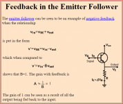
The way it is normally understood in the literature and the technical community is as follows. The signal effective input for an emitter follower is the signal Vbe. Since the B is the signal input and the E is the 100% output, emitter followers are considered to have 100% local feedback.
The proof is that all the usual feedback advantages, like increased Zin, decreased Zout, decreased distortion, increased bandwidth, are all present in an emitter follower.
Jan
Are you sure you are not missing something?Hey guys thanks for the response, I may want to conclude that change in supply voltage dosen't effect sound quality and its better to have lower voltage outputs with higher bias current.
Does a resistor use 100% NFB?
When people are talking about using NFB in a circuit they aren't really talking about resistors.
Not sure what your point is or whoever you are addressing, but I don't think you can tie the concept of feedback to a single component. Feedback is in my view a circuit property.
For instance, the 100% feedback of an emitter follower we discussed before is taught to students at Georgia Tech as the attached.
Jan
Attachments
Hi
I believe that for a given circuit, higher supply voltage generally produces lower distortion, which is borne out in both simulation and real-amp measurement. Sometimes it depends on the circuit how much improvement will be gained with the increased supply, but it is generally an inexpensive and simple way to improve performance.
For the DIYer building one amp for his/her own system - or even multiple amps if required, there is no real economy in skimping on the supply voltage. Self tends to nickel and dime his designs since his world is mass-production and it makes sense to skimp, especially since most buyers do not hold on to those creations for very long.
SMY* Thanks for your explanation!
I come to think you mentioned in an earlier post you were using your circuit in a SE configuration, in combination with high voltage and cap coupled gain stages it looks like an inspiration from tube amplifier circuits, is it? You may have already come across Nelson Pass circuits one will notice many of his simple circuits have an apparent similarity with tube circuits too.
Regarding your original question I don't have so much to add though a bit of voltage headroom makes gain stages become a bit more linear, except that high voltage circuits requires transistors which can withstand a higher voltage, but with higher voltage the current may need to be decreased in order to not exceed a given power dissipation limit, also there are a few fine audio transistors which doesn't exist in high voltage configurations, so there are both pros and cons.
Anyhow, I think what you are doing is a path worth to explore.
Regarding the expression "feedback/NFB" I understand what you mean so no problem for me, from a casual daily speech point of view at least I use to see the use of the word/abbreviation "feedback/NFB" in the context of a "circuit level" discussion, that opposed to "component level", meaning that the feedback path is taking an external way around the active component encompassing more than one node, the rest while correct is just academic Aspberger, drivel and nonsense.
Jia you!
Last edited:
- Status
- This old topic is closed. If you want to reopen this topic, contact a moderator using the "Report Post" button.
- Home
- Amplifiers
- Solid State
- PROS? High Voltage VS Low Voltage Amp