That amplifier sounds very interesting, OnAudio, you're making the right noises about its capabilities. In particular, that you can go to high volumes with no or little change in apparent tonality, an excellent marker. I shall investigate further ...!!Its interesting that the SYMEF gets loud without clipping. And is pleasurable too. People you need to experience this amplifier.
")
Frank
Hard to keep up.
I really like you train of thought. I've been trying to keep on this thread, but posts are coming faster than I can read them.
Your design methodology makes sense, and is basically used in high speed design both analog and digital. What you are proposing as important almost points towards a switching supply, where small amounts of very low impedance capacitors could suffice in ripple filtering (As high speed caps with low impedance are practically a requirement). With a small supply, those little low impedance caps could be right next to the amp, with minimal feed impedance by wiring.
I agree with your assessment of transient response. I am coming to believe that phase linearity in the amplifier (i.e. constant delay vs. frequency) is extremely important in good reproduction. However good phase linearity may be hindered by a poor supply. I believe you are right in your assessment that the rising edges and falling edges of high dv/dt waveforms is crucial in faithful reproduction. Power supply and power supply feed impedance is most likely very important.
Some attention needs to be paid to capacitor construction in this thread. Many technologies exist, some exhibit horrible microphonics, some change capacitance with applied voltage, and many have extremely high impedance values. Even the geometry for an existing technology should be assessed . Consider a 1000uf aluminum electrolytic that is tall in skinny vs. one that is short and fat in their construction.
I'll be trying to keep up with interest!
Dan
Tom,The high currents should probably be confined to small-geometry local loops whenever possible. And I still think that transient response accuracy ("speed"?) is what separates the merely great amps from the exquisite ones. After all, it appears to be relatively easy to make an amp with vanishingly-small THD (i.e. almost-perfect steady-state response) that still doesn't sound good-enough. So therefore the key must be in the transient response, right?) So focusing on decoupling cap configurations seems like a key, to me, which has been neglected too much, by most (apparently). It's not always easy to get the decoupling good-enough, even at audio frequencies, especially when high currents are involved. It usually requires accuracy to hundreds of kHz and the physical geometry becomes a significant problem, with most DIY construction methods. The main thing there is to even think about it in the first place, and actually calculate the minimum required decoupling capacitance AND the maximum tolerable inductance in its connections. THEN we might see that it's sometimes VERY difficult to get a low-enough impedance to be seen by the pins where it's needed.
It's ridiculous to talk about a PSU's low output impedance without also talking about the inductance of the conductors from its output to the load, for example, and about what the load's actual impedance vs frequency requirements are, specifically, and at what current levels.
I really like you train of thought. I've been trying to keep on this thread, but posts are coming faster than I can read them.
Your design methodology makes sense, and is basically used in high speed design both analog and digital. What you are proposing as important almost points towards a switching supply, where small amounts of very low impedance capacitors could suffice in ripple filtering (As high speed caps with low impedance are practically a requirement). With a small supply, those little low impedance caps could be right next to the amp, with minimal feed impedance by wiring.
I agree with your assessment of transient response. I am coming to believe that phase linearity in the amplifier (i.e. constant delay vs. frequency) is extremely important in good reproduction. However good phase linearity may be hindered by a poor supply. I believe you are right in your assessment that the rising edges and falling edges of high dv/dt waveforms is crucial in faithful reproduction. Power supply and power supply feed impedance is most likely very important.
Some attention needs to be paid to capacitor construction in this thread. Many technologies exist, some exhibit horrible microphonics, some change capacitance with applied voltage, and many have extremely high impedance values. Even the geometry for an existing technology should be assessed . Consider a 1000uf aluminum electrolytic that is tall in skinny vs. one that is short and fat in their construction.
I'll be trying to keep up with interest!
Dan
...multilayer heavy-Cu PCBs for my designs, I always twist wires (plaiting works great for a center-tapped winding) and prefer to use planar transmission lines (our DC bus caps were bolted to a pair of 2mm Al (or Cu for the big ones) plates separated by 1mm lexan. its pretty easy to get stupidly low inductance like that.
...many in parallel - low ESR, low ESL, lots of surface area for cooling) caps, a planar transmission line to the amp with a bit of series R, and another parallel cap bank at the amp.
most of the audio amp layouts that I have seen have been single-sided and appallingly bad. actually, thats unfair - almost every PCB layout I've ever looked at has been bad. minimum PCB cost is not necessarily optimum wrt EMI.
I believe you are spot on here. Board layout is as important as circuit design. Type of capacitor, and number in parallel. It's amazing what a few uF of SMT capacitors can do.
I agree that a lot of boards are poorly designed. Spend some time looking at some RF layout for the 2-3Ghz range. Build a few circuits for that range, and you'll get to see how important layout is!
Will be following with interest...
The three worst things that I often see in diy power amplifier board and circuit designs:
1. Input signal and input signal ground are not kept as close together as possible, everywhere.
Ditto for AC mains pair, pairs from secondary to rectifier to caps, DC power/gnd pairs, output pairs. If they are in wires, twist them tightly together, all the way from end to end. If they are on a PCB, keep the traces right next to each other, or (better) right on top of each other on opposite sides of the board (or in adjacent planes), or put one of the pair on a plane, either all around the other or above or below it, everywhere.
If there is any open space between the input signal and its ground, ANYWHERE, then they have "enclosed loop area".
A time-varying magnetic field in the air will induce a corresponding time-varying current in a conductive loop, in proportion to the geometric area enclosed by the loop. (Part of Faraday's Law and Maxwell's Equations.)
But also: Any loop with a time-varying current will induce a time-varying field in the air, in proportion to the geometric area enclosed by the loop.
So sometimes they are mostly receiving antennas and other times they are mostly transmitting antennas.
Don't make antennas! Keep all pairs TOGETHER, very close together, everywhere and always!
2. Shared ground conductors:
All conductors have parasitic inductance and resistance. A time-varying current flowing in a conductor will induce a voltage, across the inductance, that is proportional to the time-rate-of-change of the current, i.e. v = L di/dt. (Note that the induced voltage can be large even if the current is small, as long as the current's amplitude is changing fast-enough. And the current will also induce a voltage proportional to the resistance, i.e. v - iR .
If the conductor is a ground-return conductor, then the voltage back at the non-ground of the conductor will not be "ground". It will be a time-varying voltage.
If the amplifier small-signal input ground reference point shares that conductor, or part of that conductor, on its way to the main ground, and that ground-return conductor carries the currents from, for example, the decoupling capacitors' ground and/or the output/zobel ground, then the input small-signal ground-reference point for the amplifier will be a time-varying voltage, which will effectively be ARITHMETICALLY SUMMED with the input signal. That would be "a BAD thing".
Use star grounding. Keep the input signal ground separate from the other grounds. Run a completely-separate ground conductor all the way from the input signal ground to the star ground point.
3. Improper Decoupling Capacitor Configuration:
In addition to a high-frequency bypass cap right across the pins, use enough decoupling caps, with low-enough inductance in their connections to the device (i.e. close-enough!), right at each power output devices power and grouund pins.
Tom,
20 years ago I was able to do some good enough etchings, but on my attempt last year was a complete disaster transferrin from different medias and I got discouraged In the meantime I did scribed PCB’s which are less than good enough. I will follow your link with an open mind and maybe I can do again. Regarding double sided mmm but can try…that would awesome.
My layouts (art work) are done on autocad which I’m very familiar with. At different times I have tested a number of dedicated software from sophisticated to more humble ones but I did not feel comfortable with them and I guess mainly because of poor libraries. Now I have a simple one loaded on the PC Design Spark which is free but haven’t tested it. I know some other guys also use acad for their work too but of course a dedicate program should be easier to use.
Since I’ll be going to F5T V1 I will try that DesignSpark prog and see what happens.
Thanks for your encouragement
Cheers, Tony
All,
Attached are the four files for a very simple power supply test-simulation. I have much-more-detailed ones that I will upload soon. But this one will get everyone started.
I'm late to the party and haven't made it through the entire thread, however here is my contribution from almost 3 years ago to simulation on this topic:
AC to DC Power Supply - diyAudio
This is just a very basic model and can easily be extended to include the effects of ESR, lead inductance, etc. The amount of rail droop with real music is significant - granted what I used was very bass heavy.
Tom,
20 years ago .....I know some other guys also use acad for their work too but of course a dedicate program should be easier to use.
Cheers, Tony
Tony,
your are not alone. Problem with ACAD is that you need to memorize the net-list . In a dedicated PCB program the layout is referenced against the schematic which makes a big difference.
The design spark program is not bad at all. I use the commercial version called EasyPC Win. What may be nice but also restrictive of design spark is that the libraries are tied in with RS Components.
a pair of plates separated by 1mm lexan.
Just think how stupidly easy it is for a DIYer to make bus bars like that (instead of a bowl of spaghetti)
That amplifier sounds very interesting, OnAudio, you're making the right noises about its capabilities. In particular, that you can go to high volumes with no or little change in apparent tonality, an excellent marker. I shall investigate further ...!!
Frank
Welcome to the club
Thanks very much for pointing that out, mightydub, I've just started playing with what you put up. As a simple start, just adding ESR to the smoothing cap's ...I'm late to the party and haven't made it through the entire thread, however here is my contribution from almost 3 years ago to simulation on this topic:
AC to DC Power Supply - diyAudio
So, now be afraid, be very afraid ...!!!
What I did was use a jazz track WAV file to drive the current in the load resistor, in other words, a real world situation!
This is rough, very rough, but gives a starting point to show what happens in real components ...

Woah!! Scary stuff, what does this show? The top pane is the +V voltage rail!: green is when ESR of the 35,000uF smoothing caps is 30mR, a quite excellent figure for a typical electrolytic, blue is 3mR, red is 0.3mR. Bottom pane is the driving audio track, the voltage across the load resistor; a high volume but one that the amp should deal with ...
To "prove" this is not a fake, then go to the end of the track, audio drive drops to zero -- we then get the classic, textbook ripple across the smoothing cap, voltage building up again to unloaded level ...

Now, zoom in to a small part, and really see how the load current is badly upsetting the voltage rails:

This is the real world, and we haven't even looked at any of the other parastics in the game, yet ...
Frank
Whoops ... I did say this was rough ...Nice work. The voltage doesnt even drop by 2 volts
!!I forgot to bypass the soft start, the initial condition's voltage was set to 69V to get a reasonably straight waveform; to get a better idea of what the unloaded rail would look like:

Frank
Frank, do you concur that the power rails are modulated by the output current and that this can be observed in the time domein. It will be heard as well, but it may not be distiguisable from the signal in the frequency domein.
Frank, it would be interesting swapping out some capacitors to establish a cap size per amp of current required that would provide the most sensible choice.
Secondly, a single large cap could have higher ESL than several smaller caps in parallel and would prove what Tom and the guys were promoting by splitting caps into smaller equivalent value and startegically placing them on the board.
Last edited:
Hi, Nico.Frank, do you concur that the power rails are modulated by the output current and that this can be observed in the time domein. It will be heard as well, but it may not be distiguisable from the signal in the frequency domein.
Frank, it would be interesting swapping out some capacitors to establish a cap size per amp of current required that would provide the most sensible choice.
Secondly, a single large cap could have higher ESL than several smaller caps in parallel and would prove what Tom and the guys were promoting by splitting caps into smaller equivalent value and startegically placing them on the board.
Indeed the rails are modulated, and it is strongly dependent in the first instance by the ESR, the lower the effective value the better. The impact of varying ESL is not anywhere as great, I'll put up examples tomorrow.
This is all very definitely pointing to the value of using multiple small caps in parallel, something I did years by a far more seat of the pants approach, and for a very definite subjective improvement.
What I've just been doing is swapping out the pure class B current sources, and inserting the output stage of Bob Cordell's THD20 amp. Might as well use the real thing, and see what happens!! And it's looking very interesting ...
Getting very late, so I'll post this variation tomorrow, when my head's a bit straighter ...
Frank
Okaaay, got something a bit closer to a real class AB amp working, driving the power supply, and this is combining mightydub's power supply sim, and the back end of Bob Cordell's posted LTspice model, from another thread here:

Note that this sub-section of the amp, which is mirror reversed compared to how normally shown, to match the original class B source, is merely a current amplifier, no voltage gain here. The VAS, so to speak, is device E1, an ideal voltage gain stage, shown here with a gain of 75. Again, the source input is a jazz track WAV. And there's no feedback, so there would be a fair bit of distortion if you looked closely, but that's not the point at the moment, we're looking at what's happening to the power supply.
First off, to show this is true class AB, we'll drop the gain to 7.5, where the output devices are sharing the current drive to the load much of the time:

This is not taxing the supplies severely, but there is still quite a bit of noise on the voltage rail; power supply as before, with ESR of the smoothing caps at 30mR, a quite realistic figure:

Now, we'll drive the output stage hard, push it heavily into class B territory, by upping the gain to 75:

Note the output transistors are really switching off hard now, but that's not the real story, here's what's happening to the voltage rail because of the high current drain:

Next will be to start playing around with the parasitics, and the smoothing circuit area, to see what can be done to help matters ...
Frank
Note that this sub-section of the amp, which is mirror reversed compared to how normally shown, to match the original class B source, is merely a current amplifier, no voltage gain here. The VAS, so to speak, is device E1, an ideal voltage gain stage, shown here with a gain of 75. Again, the source input is a jazz track WAV. And there's no feedback, so there would be a fair bit of distortion if you looked closely, but that's not the point at the moment, we're looking at what's happening to the power supply.
First off, to show this is true class AB, we'll drop the gain to 7.5, where the output devices are sharing the current drive to the load much of the time:
This is not taxing the supplies severely, but there is still quite a bit of noise on the voltage rail; power supply as before, with ESR of the smoothing caps at 30mR, a quite realistic figure:
Now, we'll drive the output stage hard, push it heavily into class B territory, by upping the gain to 75:
Note the output transistors are really switching off hard now, but that's not the real story, here's what's happening to the voltage rail because of the high current drain:
Next will be to start playing around with the parasitics, and the smoothing circuit area, to see what can be done to help matters ...
Frank
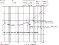
here's an output impedance plot for the LVDC bus on a +24V 100W smps. Both layouts are on a 4-layer 2Oz 1mm thick FR4 PCB. the Rev 1 (Red & Blue) layout had a small bank of X7R caps at the rectifiers, but the layout was not as good. The rev 3 layout (black) was re-arranged such that the load current was shared more evenly, and the X7R caps were moved to the load end.
Both measurements were taken at the load, with the rectifiers removed, scale in dB-ohms. although the sharp impedance trough in rev 1 might look like a good thing, in practice it means there are some complex resonances involved which are poorly damped - never a good thing. rev 3 reduces the impedance swing by 10dBOhms and its fairly well damped.
thats only 9*560uF 35V RubyCon ZLH caps = 5mF, and |Z| = 10mOhm @ 5kHz. Layout is important, but its clear that 50mF should drop this down to below 500Hz. LF performance is the parallel combination of the DC bus impedance and the transformer/rectifier output impedance, but I havent got any convenient plots to share.
this DC bus was designed to provide a specific lifetime at a given ripple current, with a nasty height constraint, for the output of a PFC flyback converter. Measured with an HP3577A + HP35676 50R signal divider. full one-port calibration at the DUT (I have a set of DIY "calibration standards" with vertical SMA sockets, and I attach an SMA socket to the DUT so the interconnect is pretty much excluded)
Attachments
Last edited:
Okaaay, got something a bit closer to a real class AB amp working, driving the power supply, and this is combining mightydub's power supply sim, and the back end of Bob Cordell's posted LTspice model, from another thread here:
<snipped>
Note that this sub-section of the amp, which is mirror reversed compared to how normally shown, to match the original class B source, is merely a current amplifier, no voltage gain here. The VAS, so to speak, is device E1, an ideal voltage gain stage, shown here with a gain of 75. Again, the source input is a jazz track WAV. And there's no feedback, so there would be a fair bit of distortion if you looked closely, but that's not the point at the moment, we're looking at what's happening to the power supply.
First off, to show this is true class AB, we'll drop the gain to 7.5, where the output devices are sharing the current drive to the load much of the time:
<snipped>
This is not taxing the supplies severely, but there is still quite a bit of noise on the voltage rail; power supply as before, with ESR of the smoothing caps at 30mR, a quite realistic figure:
<snipped>
Now, we'll drive the output stage hard, push it heavily into class B territory, by upping the gain to 75:
<snipped>
Note the output transistors are really switching off hard now, but that's not the real story, here's what's happening to the voltage rail because of the high current drain:
<snipped>
Next will be to start playing around with the parasitics, and the smoothing circuit area, to see what can be done to help matters ...
Frank
How about posting the .asc file(s)?
What diodes are used in the bridge? Maybe right-click on them and put some "real" power diodes in?
Need to model at least the main power-rail conductors, between the smoothing caps and the load, as series inductance and resistance (25 nH and 1 mOhm per inch).
Lower priority: Maybe try two of my transformer model, or similar, since the one being used doesn't have leakage inductance. (Might need a snubber, then, however.)
If yo ustart using large smoothing capacitors you then need to think about power on surge blowing fuses. People then add anti surge circuits which is fine but I have lost count of the number of threads where teh anti surge circuit had gone wrong.
I prefer to use lesser smoothing and get rid of the anti surge circuit. A good design will reject ripple on the power supply.
For 100watts I would use 2 off 4700uf capacitors.
I prefer to use lesser smoothing and get rid of the anti surge circuit. A good design will reject ripple on the power supply.
For 100watts I would use 2 off 4700uf capacitors.
- Status
- This old topic is closed. If you want to reopen this topic, contact a moderator using the "Report Post" button.
- Home
- Amplifiers
- Power Supplies
- Power Supply Resevoir Size