I wouldn't touch a screw top or pronged cap for power supply duties; only multi-paralleled, radial leaded units for me, for a decade now. Even the cheap units drop sufficiently in effective ESR for this to work ...I don't have Cyril Bateman's tan-delta-meter and I haven't been so methodical.
I was commenting on experience, OK many years ago, when only LCR electrolytic capacitors had significant ESR for a Linear simple rectified power supply though they were cheap.
The Nippon Chemi-con capacitors that were generally used had a low enough ESR that the effect on the wave form was largely absent.
Frank
And I've just run through some of your "vigorous" input in that thread - we are on the same page!! I've done a lot of thrashing myself using LTspice, that duplicates in many areas the sort of things you were so passionately researching. So, I know exactly why you were beating the drum about current requirements as strongly as you did, and the need to acquire full understanding of all the parasitics in the equation ...
Frank
Hallelujah!!! I have to say that I suddenly feel much better, like I'm not so alone any more!
I feel like I have basically only had time to dabble at all of this stuff. So I hope that you already have a lot more of it figured out than I do and can clue me in on where it leads, what's important or significant and what's not, etc etc etc.
I am smiling at your description of the tone and intensity of my posts about the decoupling and parasitics stuff. You are right. I felt sort-of like I had found a treasure that had been right under everyone's noses all along, and it almost felt like I was somewhere where I only had to take a few steps to be in a crowd of people again, and I was saying "Hey, guys! I found a treasure, RIGHT over there, but there's so much gold that I can't begin to carry it all! Come get some!" and was amazed that no one was very interested (although there were a couple of much-appreciated exceptions).
I'll PM you!
There's at lot to learn here....capacitance falls radically with frequency, impedance rises with frequency as the caps turns inductive...hmm...This much more than I had expected. having polypropylene's/ceramic as final reservoirs seems almost mandatory..what is superb spec's worth, if there's no current to deliver.
Well, one bright spot is that the caps that you might want to use for the frequencies where the electrolytics go south might at least TEND toward being smaller values, since the frequencies are higher. (Or, in some types of circuits, you could just use more electrolytics.)
That also illustrates one reason why real designers somtimes use a lot more electrolytics than we might at first believe they need: because they want them to still work well-enough even when at temperature extremes, from DC up to 10 kHz or more.
seems to me that opc has been aware of this stuff for a while too. his designs may not be creative marvels, but IMO they are application genius. bulk low esr onboard and local supply caps backed up by further bulk 4.7->10uf ceramic directly on device pins with multilayer boards enabling the whole PCB to be very small, particularly as SMD is not a dirty word.
Last edited:
Thanks for this finding. It's worth more investigation.
Is it not a good way to determine the optimal value of the reservoir cap such as the peak in the waveform with ESR does not show up ?
forr,
It can be a very good way for doing many things SIMILAR to that, too. And you could do THAT (what you mentioned), also, very easily, if you desired to do it. (see attached)
LT-Spice is a free download, from Linear Technology - Home Page . And many people believe it's better than most or all of the commercial spice simulation software. There is also a very good USER SUPPORT GROUP fror LT-Spice, at yahoogroups.com .
Anyway, using spice effectively is an art that would need to be learned. But I do firmly believe that it is WELL worth the time and effort.
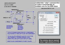
Going back to your original question: It would be trivial to parameterize (i.e. make a variable for) the ESR (and other parasitics if desired) in the capacitor in my LTSpice schematic, and then tell spice to step the parameter, either according to step size and start/end steps, or, according to a list of step values that I provided. Then when I click the "run" button spice would automatically perform multiple simulations and churn through all of the steps without stopping and would then display all of the waveforms on one plot on the screen. I could have actually done it in about the same time as it took to type this paragraph. (I'll do it and be right back, just so you can see the waveforms, and imagine the myriad possibilities!)
I attached the plot, and also attached the schematic from the LT-Spice software (with some text I added in Paint), that made the plot. I'm sorry about the colors and the brightness in the images. They are much dimmer than they are on my computer, on the original LT-Spice software's screens.
LT-Spice is really great. You can just draw a schematic and then click the RUN button, to simulate it. During or after a simulation run, your mouse cursor is a probe! Touch any conductor and the voltage there is instantly plotted (like the original plot I posted, for example). Move the probe over a component or where a wire enters a component and you can plot current. Hold down Ctrl and you can plot dissipation! Right-click on a plot label and enter any equation you want to plot, involving anything in your circuit! Place your mouse pointer on a plot and it reports the values. Click and drag and it gives differential measurements. Drag a box and let go and it zooms in on the waveform. After a run, you can have it integrate or average a plot (or equation), or a zoomed portion, and you can have it do an FFT just as easily. Or you can run a whole simulation in the frequency domain, then do most of the same types of manipulations, with a plot vs frequency. And it can even use WAV files for input and output, if you want! (Just imagine: When personal computers get to be fast-enough to run LT-Spice in real time, with WAV file inputs and outputs, we could just draw a schematic and then listen to it immediately.)
I have only just barely "scratched the surface" of the capabilities, here!! There is so much more that it would take a book or two to describe it all.
Did I mention that LT-Spice is totally FREE? Zero cost! Free download! Linear.com.
Cheers,
Tom
Attachments
Last edited:
seems to me that opc has been aware of this stuff for a while too. his designs may not be creative marvels, but IMO they are application genius. bulk low esr onboard and local supply caps backed up by further bulk 4.7->10uf ceramic directly on device pins with multilayer boards enabling the whole PCB to be very small, particularly as SMD is not a dirty word.
Sounds perfect! Actually, there are a whole lot of people who live and breath this stuff, but not so many in the diy audio realm. I have been trying to take a slightly different tack, which was to see how it could (or should) be applied when you DON'T have multilayer boards and SMD (or maybe even no pcbs at all), so that the many people who hand-build all of their stuff could benefit.
Gotee,
Thanks for your advice. I use Tina where the SPICE aspect is a bit more transparent to the user than LT-SPICE, making drawing and runing simulations somewhat easier, at least for me.
However, what is important is that I could duplicate your schematics in a few minutes, finding the same results. I now know where to look at with real components.
Regards.
Thanks for your advice. I use Tina where the SPICE aspect is a bit more transparent to the user than LT-SPICE, making drawing and runing simulations somewhat easier, at least for me.
However, what is important is that I could duplicate your schematics in a few minutes, finding the same results. I now know where to look at with real components.
I thought of this a while ago, Tina has this feature too, I did not use much yet. It could be very nice in many applications.Just imagine: When personal computers get to be fast-enough to run LT-Spice in real time, with WAV file inputs and outputs, we could just draw a schematic and then listen to it immediately.)
Regards.
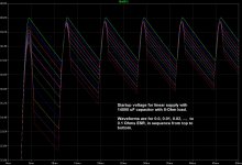
Just did a quick LTSpice simulation of a 40V linear power supply with a 14000 uF reservoir cap and an 8 Ohm load, with no ESR and with 0.1 Ohm ESR. The attached ripple voltage plot shows the effect. It's due to ESR.
Yes, and not only capacitor ESR, also negative and positive connections can give similar effects: I like to scope measure amps between chassis and the electrolytic negative pole - of course this applies to single PS amps. Sometimes I get an absolutely flat line (e.g. Marantz 1030), but more often I see bumps when the capacitor charges (e.g. on a Sanyo DCA 200). These bumps added to the ideal shape give that distorted shape.
power supply stitching
Hi Tom,
Check this out")
http://www.diyaudio.com/forums/soli...eon-mode-2diffef-amplifier-2.html#post3100335
Hi Tom,
Check this out
http://www.diyaudio.com/forums/soli...eon-mode-2diffef-amplifier-2.html#post3100335
I attached the plot, and also attached the schematic from the LT-Spice software (with some text I added in Paint), that made the plot. I'm sorry about the colors and the brightness in the images. They are much dimmer than they are on my computer, on the original LT-Spice software's screens.
LT-Spice is really great. You can just draw a schematic and then click the RUN button, to simulate it.
Ah, but a shematic of what?
On your schematic (and I am aware it is simple for demonstration purposes of parametrisation) check the values of diode currents...
You are, hopefully, aware that real world sources like transformers have many parasitic components (resistance, stray inductance, stray capacitance, saturation current etc...). Capacitor ESR is often a relatively minor variable compared to winding resistance and sometimes even diode resistance, and to make matters more interesting, it can be non-linear (highly so as ripple current approaches upper limits for your chosen caps). Capacitor ESL also likes to play tricks making resonant circuits on one, and stray capacitances/inductances of a transformer on the other side of commutating diodes, with diode recovery adding a nice interdependency to it all...
Yes, the fantasy that a power supply just produces an easily understood ripple voltage does no-one any favours; it seems that nobody else has ever listened, as in using their ears, to the glorious song that the supposed DC voltage rails are giving voice to when they're being driven hard by real audio signals.You are, hopefully, aware that real world sources like transformers have many parasitic components (resistance, stray inductance, stray capacitance, saturation current etc...). Capacitor ESR is often a relatively minor variable compared to winding resistance and sometimes even diode resistance, and to make matters more interesting, it can be non-linear (highly so as ripple current approaches upper limits for your chosen caps). Capacitor ESL also likes to play tricks making resonant circuits on one, and stray capacitances/inductances of a transformer on the other side of commutating diodes, with diode recovery adding a nice interdependency to it all...
But, simulation will do the job, and give great insights, IF you include all the parasitic and non-linear behaviours. Simple model, almost meaningless results; complex, ever more accurate modelling -- there are no limits as to how sophisticated the model can be made -- will give you Ah-haa!! moments ...
Frank
Ah, but a shematic of what?
On your schematic (and I am aware it is simple for demonstration purposes of parametrisation) check the values of diode currents...
You are, hopefully, aware that real world sources like transformers have many parasitic components (resistance, stray inductance, stray capacitance, saturation current etc...). Capacitor ESR is often a relatively minor variable compared to winding resistance and sometimes even diode resistance, and to make matters more interesting, it can be non-linear (highly so as ripple current approaches upper limits for your chosen caps). Capacitor ESL also likes to play tricks making resonant circuits on one, and stray capacitances/inductances of a transformer on the other side of commutating diodes, with diode recovery adding a nice interdependency to it all...
ilimzn,
Thank you.
Of course! I am glad to see that you appreciate the importance of parasitics and non-linearities. Ironically, I have usually been the one who has been reminding everyone else to consider them!
That schematic and simulation were meant to illustrate ONLY the ESR's simplest effect on the ripple voltage waveform. Read back a few pages to forr's posts. We were trying to help him identify and understand the cause of the shape of a ripple-voltage waveform that he had measured. I was merely showing that it was caused by the ESR of one of the caps that he was using, and responding to his question about the possibility of varying the ESR to see how that affected the waveform (and trying to convince him to start using LT-Spice).
Regards,
Tom
now if you only could repeat the test with an amplifier included and all the parameters set.
tsiros,
Well, OK, but what would you want to see, from that? Actual versus Expected Voltage across the load, maybe? Current waveforms of capacitors and diodes? But under what conditions?
I certainly "could". And I have, many times. And there are others here who are professionals at that, compared to me.
And it's been a few years. Back then, I used fairly-decent transformer models, too, and inserted all of the parasitics I could, for the components as well as for all of the conductors (power, ground, and signal), and even connected speaker models (and speaker CABLE models), and had mains wiring models on the other end. Sometimes I even used the frequency- and temperature-dependent electrolytic capacitor models from Cornell Dubilier. I also did quite a few with switch-mode power supplies.
But it's been about four years since I did a lot of those large "all-inclusive" simulations. So the amount of time it would take to dig out some old files and try to get back up to speed, well-enough to come up with something that I thought was worthy of posting (and not overly easy for people to criticize), makes me hesitant to commit to doing that, especially in the near-term timeframe.
Lately, I've mostly been making it much easier on myself, and simpler, by simulating the smallest bits of a system that I can, in order to understand some particular thing's effects (WHEN I actually have the time to pursue this hobby).
When the amplifier is not the main point, for example, I usually just throw in a chipamp model or some kind of ideal current sink or hold-off-voltage source and a resistor, as the load. The OPA541E chipamp spice model, for example, models much of the power pins' behavior (unlike many amp and opamp models that are out there). But simple ideal sources often work even better, for just looking at the supply, decoupling caps, and power/ground rails.
I'll see what I can put together that's simple but still includes a lot of the effects. How about a transformer model, diode bridge, reservoir caps, and a load that tries to let sine waves or pulses of current flow, through a low resistance? I could probably make one model that has no parasitics in the conductors and one that does, for comparisons. Oh, how about one with and without sufficient decoupling caps? Once the models are in place and running, it will be relatively quick and easy to add and remove capacitors, and things like that.
I'll slap something together and report back.
I'll also post the actual model files, so everyone can play with them and try their own tweaks and mods.
Cheers,
Tom
Way to go, Tom, I'll be interested in what you come up with. Do you include the scenario that most mains voltage waveforms are a mess, a long way from the beloved pure sine wave of the textbooks ...?I'll slap something together and report back.
I'll also post the actual model files, so everyone can play with them and try their own tweaks and mods.
Cheers,
Tom
Frank
Way to go, Tom, I'll be interested in what you come up with. Do you include the scenario that most mains voltage waveforms are a mess, a long way from the beloved pure sine wave of the textbooks ...?
Frank
I did include different types of junk summed with the mains, in the past.
I am going to stay as simple as I can, at first at least.
Wow. That is a very-nice-looking layout. I will have to keep that one to study.
Hi guys,
Here is an example of some of the ideas discussed on this thread regarding local decoupling. I'm working on this F5 layout since I might be doing a second amp. This layout is not finished and there are several errors in it so this is just to show one way to accomplish the local decoupling using 47u + 220u + 2200 or 4,700u and would like to hear your comments.
On the running amp I have decoupling done with 4,700u plus a film 0.1u which I will replace in the future with a 220u and see if I can here differences. The PSU is quite heavy with a couple of 800VA trafos and a CLC filter feeding both channels.
The new amp will have only one trafo and a similar CLC PSU
What do you think?
Cheers, Tony
Attachments
Last edited:
- Status
- This old topic is closed. If you want to reopen this topic, contact a moderator using the "Report Post" button.
- Home
- Amplifiers
- Power Supplies
- Power Supply Resevoir Size