temp problem solved
hello again,
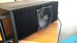
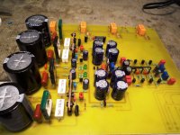
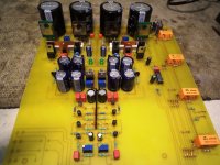
i have installed two very quiet fans on those heatsink and now the idle temp. after about half hour is about 45C at the highest point (before was about 65). those fans are from be-quiet a german company which makes very quiet fans. I run the fans about 7.5V each and they are 14cm in diameter.also i opened the case after about 1 hour at idle and the capacitor temperature is about 38-40C. Now i think it will be ok.
hello again,
i have installed two very quiet fans on those heatsink and now the idle temp. after about half hour is about 45C at the highest point (before was about 65). those fans are from be-quiet a german company which makes very quiet fans. I run the fans about 7.5V each and they are 14cm in diameter.also i opened the case after about 1 hour at idle and the capacitor temperature is about 38-40C. Now i think it will be ok.
Attachments
Now i think it will be ok.
With the sensitivity of your loudspeakers, very likely.
I wouldn't underestimate the dissipation of your power amps when loaded though.
Due to the 70Vdc rails, max dissipation is pretty steep compared to power amps with bipolar output stages, and is superimposed on the idle dissipation level,
hello again,
i have installed two very quiet fans on those heatsink and now the idle temp. after about half hour is about 45C at the highest point (before was about 65). those fans are from be-quiet a german company which makes very quiet fans. I run the fans about 7.5V each and they are 14cm in diameter.also i opened the case after about 1 hour at idle and the capacitor temperature is about 38-40C. Now i think it will be ok.
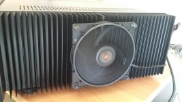
I see you have those fans in the middle (where your outputs are).
That's another hard learned lesson for me. Spread those pairs out , the extrusions
will conduct better and any single pair will have the same thermals as the next.
With many pairs close together , middle devices will be hotter - end ones cooler.
On BJT's , Vbe will be different on the paralleled devices. Amp will work , but
if you were to approach thermal limits , one pair would fail prematurely (the
hottest ones).
PS - your fan in the middle most likely equalizes this thermal deficiency. Without it ,
center could be >10C hotter than the ends.
OS

One may ask me why i continue to make my amps based on 2SA1302 2SC3281 outputs ...
Answer is very simple
BECAUSE I CAN
C'mon, everybody know you have quite a stock of those transistors...
(I have only 4 pairs of those, taken from a Pioneer receiver)
Hi,
It's always nice to have parts you are comfortable with, no doubt. However I did discover that the current ON Semi parts are more than satisfactory. It would be nice to have a pile of parts already paid for!
Why the 10 turn bias control? Those aren't reliable compared to the normal single turn types. The range of control can easily be made to cover what you need so it isn't hard to adjust. Just asking, that's all.
-Chris
well Chris you are probably right even though not important those give a feeling of extreme precision which is a small obsession.
the wise thing to do is a fixed resistor or a resistor with a trimmer in series in order to be able to move within small acceptable range .
I loved some Japanese amplifiers that have for example 15 mv bias over resistor X and the '' reading " of the trimmer is exactly in the middle ...
Kind regards
Sakis
Last edited:
every now and then i get the chance to be cocky
Isn't that the purpose of life.
well Chris you are probably right even though not important those give a feeling of extreme precision which is a small obsession.
the wise thing to do is a fixed resistor or a resistor with a trimmer in series in order to be able to move within small acceptable range .
I loved some Japanese amplifiers that have for example 15 mv bias over resistor X and the '' reading " of the trimmer is exactly in the middle ...
Kind regards
Sakis
I do a 390R plus a 500R bourns 10 turn trimmer (in series).
Those 500R's are set at 250R when bought new. Builder stuffs it ,
output stage is about 60ma bias. The full trimmer range
will give about 0-200ma per device
If the trimmers wiper goes bad - full 500R .... no bias. Trimmer open , also collapses
the Vbe. can't be too careful with 5 pair Sanken MT-200's.
PS - never had a reliability issue with those ten turn trimmers. My Vbe just passes
<1ma through the divider - microwatts.
OS
Last edited:
HI Pete,
I think if you read the spec sheet they might mention that the multi-turn trimmers are for potentiometer use. The wiper is not intended to pass any current. Of course, they will work just as most components will service outside their intended use. A single turn control has much higher contact area and pressure compared to the teensy tiny multi-turn trimmer control. In all <good> test instruments these multi-turn controls only serve in a potentiometer role.
The best part of a good design is that they fail open normally, so zero bias is the definition of "fail safe". In my lowly opinion, it is very easy to design the circuit that the padding resistors will restrict the adjustment range to what is needed and no more. Some of you out there may have come into contact with what we came to call "Yamaha syndrome" where the controls had far too high a range to adjust properly. For all their engineering excellence, Yamaha always seemed to fail to use a reasonable adjustment range. I think it was to save the cost of two fixed resistors. Other brands had designers that simply didn't know any better.
So it isn't the power dissipation, but the actual current flow in contacts that were not designed for this. The wiper and slip ring contact area will multiply that 1 mA into x Amperes per unit area. I haven't looked at those data sheets lately, but that was a point I noticed in one industrial range of parts. I'm quite certain someone can find a mil-spec part that is rated for current through the adjustable contact somewhere.
This is a very small point in fact. The thing that irks me is the use of multi-turn trimmer controls to sidestep the steps to figure out what the range should be. The 10-turn thing is a recent development, and they are not suited to this job.
-Chris
The bourns PTH - www.bourns.com/data/global/pdfs/3250.pdf is a 1 watter.
I'm abusing it with a whole .0002W (never actually calculated that - .2V x 1ma).
It should hold up. That little current just biases the Vbe. Vbe semi conducts most of the current.
LATFET bias trimmer might be different. It passes all the current since there is no Vbe.
For a Vbe , it's always best to scale the divider vs. semi current ratio so the semi
takes >80% of the current. An EF3 setup usually has much lower Vbe current , as well.
Edit - the PTH trimmers are MIL-R-27208's , BTW.
OS
Last edited:
I use the 25Turn versions.
I have never had a problem.
I always check the maximum current for the resistance and power rating and never take more than 50% of that current into, nor out of, any node. I have recommended to others that they never take more than 50% of power rating (=<70% of current rating) to other members
eg 2k 400mW 25Turn pot has a maximum current of 14.1mA
Therefore I would always ensure I use <7mApk.
In the Vbe multiplier duty where the VAS current is 5mA +-4mA , i.e. 1mApk to 9mApk
The transistor base, when hFE ~150, will be ~ 9/150 ~ 60uA
The resistor dividing string would have ~2k of minimum resistance, passing ~2.4Vdc/2000 = 1.2mA
A 500VR has a maximum rating of 28.2mA
The FoS is so high I can see why I have never experienced any problem.
Yes , It's very good to never have a complaint about thermal stability , ease of adjustment. It frees the discussion up for design input , SQ assessments.
The output stage should be absolutely - 100%.
Edit - Kemet and Xicon trimmers are cheaper asian parts , still - never an issue. Some I've "reharvested" many
times for new designs , never any spec issues or faults.
OS
The output stage should be absolutely - 100%.
Edit - Kemet and Xicon trimmers are cheaper asian parts , still - never an issue. Some I've "reharvested" many
times for new designs , never any spec issues or faults.
OS
Last edited:
Hi Pete,
From the data sheet ...
Bias adjustments are an imprecise adjustment since most circuits will diverge from the set current with temperature. So any idea of a precision adjustment is flawed right out of the gate. Accept this. Now, since the entire premise of using multi-turn trimmer resistors was predicated on the idea of a precise adjustment, the entire argument falls down. One thing you should note from the excerpt above is that a bias current application should use a wire-wound trimmer, not a cermet one.
I don't know about you guys, but sitting there turning a little screw for 30 sec is a complete waste of time. The required time for a single turn control is 5 ~ 10 sec as a kind average. So the purpose is mismatched, and it takes more time to physically get the wiper to the desired setting. All I see are negatives here.
Will those controls work? Sure they will. But over the long term, or when something goes very wrong in the output stage (boom, or maybe just a snap), the multi-turn control simply has less surface area with a lower current carrying capacity than the single turn variant.
"I haven't had any problems using them". Well, how do you know after the device has some years on it? You will not hear a bias variation, and you don't test the bias current level for years typically. Any current variation is written off to aging and deemed acceptable. Okay, fine. But, the fact remains that the multi-turn isn't the correct part for the application which is better suited to a single turn part.
Hi Andrew,
Yes, they make these types of trimmer in 20 and 25 turn, also 5 turn (which might be a nice compromise). Do you have a lot of trouble setting bias in your circuits? I'm trying to understand why you felt it beneficial to go for an exaggerated version of the more common 10 turn trimmer control. If anything, any negatives for using muti-turn controls will be greater for higher numbers of turns required in a control.
Anyway, the fact remains that multi-turn trimmers do not deliver any benefits in a bias control situation. In fact there are negative aspects to using them in favor of a single turn trimmer. I'll assume that people are using the more expensive parts from companies like Bourns and others. If these are inexpensive controls from Ebay, or just cheap, the possible problems outweigh any price advantage. I'll use a cheap single-turn trimmer rather than a cheap muti-turn trimmer any day!
You can use whatever you wish obviously, just don't delude yourself about whatever real advantages they bring to the table. At the beginning of this fad years ago, the argument went something like this, "pull those cheap single turn pots and put in a nice 10 turn trimmer control instead". The entire argument was centered on the belief that the single turn control was a cheap part installed to save money. Well, they are less expensive and using them does save money on the assembly line as time required to make the adjustment. But those trimmer controls were not less quality than the equivalent multi-turn controls folks bought from Ebay (be honest, that's where most of you buy them). I do use the Bourns single turn controls for bias adjustment. They aren't cheap either, but they are the correct component for this purpose.
-Chris
From the data sheet ...
The concern has always been contact resistance, not device dissipation.Stability refers to the ability of the trimmer to remain at the
desired setting. Environmental factors play an important role here:
stability may be affected by temperature exposure, thermal shock/
cycling, humidity, and mechanical shock or vibration.
This is not a matter of concern in most applications, since
Bourns trimmers exhibit excellent stability under all specified conditions.
Stability is most often a concern when cermet trimmers are
used in low current "dry" circuits (50uA amps and below). Under
these conditions the contact resistance may vary, making the wiper
appear unstable. This is most noticeable in some rheostat applications.
This can be avoided by using a wirewound unit, or choosing a
cermet trimmer that has been designed for dry-circuit applications.
Bourns applications engineers can assist you on this and other
questions.
Bias adjustments are an imprecise adjustment since most circuits will diverge from the set current with temperature. So any idea of a precision adjustment is flawed right out of the gate. Accept this. Now, since the entire premise of using multi-turn trimmer resistors was predicated on the idea of a precise adjustment, the entire argument falls down. One thing you should note from the excerpt above is that a bias current application should use a wire-wound trimmer, not a cermet one.
I don't know about you guys, but sitting there turning a little screw for 30 sec is a complete waste of time. The required time for a single turn control is 5 ~ 10 sec as a kind average. So the purpose is mismatched, and it takes more time to physically get the wiper to the desired setting. All I see are negatives here.
Will those controls work? Sure they will. But over the long term, or when something goes very wrong in the output stage (boom, or maybe just a snap), the multi-turn control simply has less surface area with a lower current carrying capacity than the single turn variant.
"I haven't had any problems using them". Well, how do you know after the device has some years on it? You will not hear a bias variation, and you don't test the bias current level for years typically. Any current variation is written off to aging and deemed acceptable. Okay, fine. But, the fact remains that the multi-turn isn't the correct part for the application which is better suited to a single turn part.
Hi Andrew,
Yes, they make these types of trimmer in 20 and 25 turn, also 5 turn (which might be a nice compromise). Do you have a lot of trouble setting bias in your circuits? I'm trying to understand why you felt it beneficial to go for an exaggerated version of the more common 10 turn trimmer control. If anything, any negatives for using muti-turn controls will be greater for higher numbers of turns required in a control.
Anyway, the fact remains that multi-turn trimmers do not deliver any benefits in a bias control situation. In fact there are negative aspects to using them in favor of a single turn trimmer. I'll assume that people are using the more expensive parts from companies like Bourns and others. If these are inexpensive controls from Ebay, or just cheap, the possible problems outweigh any price advantage. I'll use a cheap single-turn trimmer rather than a cheap muti-turn trimmer any day!
You can use whatever you wish obviously, just don't delude yourself about whatever real advantages they bring to the table. At the beginning of this fad years ago, the argument went something like this, "pull those cheap single turn pots and put in a nice 10 turn trimmer control instead". The entire argument was centered on the belief that the single turn control was a cheap part installed to save money. Well, they are less expensive and using them does save money on the assembly line as time required to make the adjustment. But those trimmer controls were not less quality than the equivalent multi-turn controls folks bought from Ebay (be honest, that's where most of you buy them). I do use the Bourns single turn controls for bias adjustment. They aren't cheap either, but they are the correct component for this purpose.
-Chris
do the math for me Chris
bench amplifier is a P3A made around 2009 working every day lets say from 10.00 in the morning till 21.00 night minimum 6days a week
Often amplifier is on but don't play and every 2 years about was checked about drift of anything capacitors bias and/or any other sign of warn or flaw ...
from 2009 and since on the same board there was a number of upgrades in the LTP . the drivers , few other details and last year we had a new power supply board while the vbe scheme has been the same since 2009
I agree 100% with your comments also with the comments on temperature based variations but still i find no harm using them and serve my obsession to spent like 15 minutes to set up the starting bias on my amplifier ...
With respect
Sakis
Hi Sakis,
I don't have a problem with someone who knows what they are doing making this choice, but I do have a problem with those people who don't understand and only see some others using the multi-turn controls. Why? Because the mindless "upgrade" industry that will take a decent receiver - amp or whatever, and take money to improve that product when they are in fact (usually) causing damage. Most of them can't solder properly to start with.
I have spent many years undoing the damage caused by (possibly) well intentioned individuals. Most often they pose as technicians, but specialize in "upgrading" equipment with ideas and procedures they read about on the internet. So, while using good quality products, you can do this to satisfy yourself, we have the sort of people who read about (say) your experiences and decide that this must be better and is a very real upgrade. Nothing could be further from the truth.
Sakis, when you do check bias current, you do see that it varies with temperature. The setting you made is approximate at best - right?
-Chris
- Home
- Amplifiers
- Solid State
- Post your Solid State pics here