the Turn Table ground/Earth should not be connected to the signals coming from the Turn Table. The signals should be isolated.
This allows one to connect the TT G/E to be connected to the Chassis, or to the Power Ground, of the Receiver without any deleterious effects.
Some TT ground the arm tube. If this is connected to the Receiver Earth, then the arm tube becomes a screen extension of the Receiver Chassis.
This allows one to connect the TT G/E to be connected to the Chassis, or to the Power Ground, of the Receiver without any deleterious effects.
Some TT ground the arm tube. If this is connected to the Receiver Earth, then the arm tube becomes a screen extension of the Receiver Chassis.
PRO EQUIPMENT IN HOME THEATER.....
As I got into home theater at age 33 or so, I quickly learned the benefits of dynamic headroom, and having individual power supplies in separate chassis. I have since been die-hard at getting the most out of my dollar. My first system used an Onkyo TX-SR 702, (3) Alesis RA500's, and a Behringer EP2500. My fronts have been custom made since my first system, and live on (though modded repeatedly) in my current system using a Pioneer Elite SC-07, a Sony 200-disc rotary player, and a PS3;as the brains and media supplies.
Amplification is as follows:
* Fronts: Each front has a Sonetic SA650 (QSC USA 1300 inside and out) bridged, about 2000 watts per channel.
* Surrounds: A Lineartech L500; 165 wpc @ 8 Ohms, 240 wpc @ 4 Ohms.
* Center: One channel of a Cerwin Vega A1800i
* Rear pair: Other channel of a Cerwin Vega A1800i
* SUB: Ashley Fet 500 early THX theater amp, 1400 watts bridged, (3)12" drivers in an 18X30 enclosure. Loud fan has been removed, and 2 Denon receiver heatsinks do the convection cooling now.
165% more energy for Sony Muteki STR-KM3
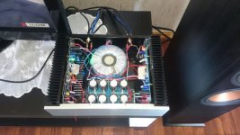
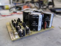
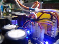
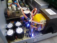
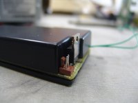
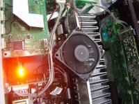
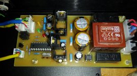
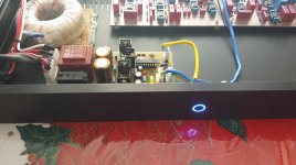
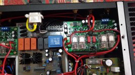
I was fixing a Sony HT Muteki STR-KM3 with a faulty power-on relay, and I decided to add a fan to cool the excessive heating drivers, and a capacitor bank to raise by 165% the energy reservoir (from 13,600 to 36,000 uF).
PWM controller inspired on a @bimo's blog post.
Capacitor bank has NTC+diode to limit inrush charging current, and a reverse diode do let energy flow backwards in each rail.
Attachments
-
 DSC01390.JPG172.1 KB · Views: 1,200
 -
 DSC01398.JPG178.2 KB · Views: 1,122
 -
 DSC01400.JPG216.1 KB · Views: 1,116
 -
 DSC01404.JPG183.4 KB · Views: 1,057
 -
 DSC01405.JPG223.4 KB · Views: 394
 -
 DSC01306.JPG163.7 KB · Views: 320
 -
 DSC01301.JPG155 KB · Views: 311
 -
 DSC01300.JPG141.5 KB · Views: 255
 -
 DSC01298.JPG186.5 KB · Views: 361
 -
 DSC01315.JPG243.9 KB · Views: 373
Last edited:
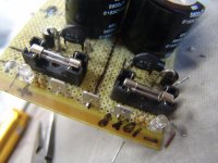
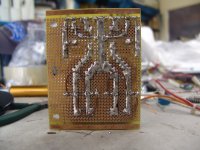
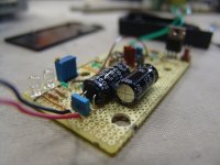
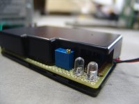
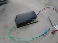
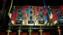
Thank you for your advice!pic3 shows 4 loops of wire connector under the circuit.
Those loops in that Nazca Lines-like tracks were the easiest way I found to parallel those resistors with the big capacitors to provide some discharging after power off.
This is a kind of add-on board, connected in parallel with the original power supply circuit. Of course there is a lack in voltage due to the diodes. But it seems to be working fine, and that the overall performance of the HT got much better.
6ch power amp
finally i have finished my active crossover and 6ch power amplifier.
the active crossover and power amp are for my 3 way speakers (using seas excel drivers) whith i am converting to active.
I am using the opa2134 opap in the active crossover and the cap and resistors are high quality.
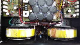
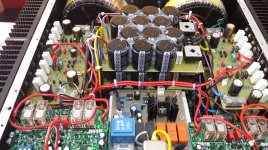
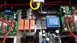
The power amplifiers is 200w/8ohm , i am using 3x600a transformers each for 2 channels and each channel has one bridge and 14000uf capacitors per rail, except the channels 1 and 2 which have 18800uF per channel per rail. I have made a circuit using micro controller to power up those transformers via ntc and then they are shorted using relays. Also the micro controller board has a circuit which senses the audio input and can power up-down the amplifier.
everything seems to work fine. i have not yet tested using my expensive speakers. So what do you think?
finally i have finished my active crossover and 6ch power amplifier.
the active crossover and power amp are for my 3 way speakers (using seas excel drivers) whith i am converting to active.
I am using the opa2134 opap in the active crossover and the cap and resistors are high quality.
The power amplifiers is 200w/8ohm , i am using 3x600a transformers each for 2 channels and each channel has one bridge and 14000uf capacitors per rail, except the channels 1 and 2 which have 18800uF per channel per rail. I have made a circuit using micro controller to power up those transformers via ntc and then they are shorted using relays. Also the micro controller board has a circuit which senses the audio input and can power up-down the amplifier.
everything seems to work fine. i have not yet tested using my expensive speakers. So what do you think?
Attachments
-
 20150611_141938.jpg365.9 KB · Views: 292
 -
 20150611_142055.jpg339 KB · Views: 360
 -
 20150611_155021.jpg367.7 KB · Views: 428
 -
 20150611_155012.jpg302.8 KB · Views: 489
 -
 20150611_155029.jpg437.7 KB · Views: 465
 -
 20150611_155049.jpg442 KB · Views: 329
 -
 20150611_155142.jpg342 KB · Views: 412
 -
 20150611_155154.jpg526.5 KB · Views: 449
 -
 20150611_155106.jpg410.1 KB · Views: 424
 -
 20150611_141920.jpg405 KB · Views: 361
Last edited:

finally i have finished my active crossover and 6ch power amplifier.
the active crossover and power amp are for my 3 way speakers (using seas excel drivers) whith i am converting to active.
I am using the opa2134 opap in the active crossover and the cap and resistors are high quality.
The power amplifiers is 200w/8ohm , i am using 3x600a transformers each for 2 channels and each channel has one bridge and 14000uf capacitors per rail, except the channels 1 and 2 which have 18800uF per channel per rail. I have made a circuit using micro controller to power up those transformers via ntc and then they are shorted using relays. Also the micro controller board has a circuit which senses the audio input and can power up-down the amplifier.
everything seems to work fine. i have not yet tested using my expensive speakers. So what do you think?
I think a lot ! Best high density arrangement I've seen. I thought stuffing two amps
was tough.
Are they high PSRR designs ? Multiples on a single PS dictate this. But , L/R
active EQ to each speaker might reduce any errata. You would then just
have the combined LF - HF ripple for just two channels. Would act
like a dual mono , in this case.
Still , good "stuffing"
 !
!OS
no there is not space for another channel neither simple capacitor
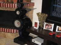
they are the AV400 class AB amplifiers. i have been using this design several years and i am very happy with that. those amps works with +- 70vdc. each channel has its own power supply.
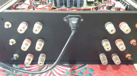
now i will work on my speakers to remove the passive crossovers and make another holes to the granite base (very difficult) for another two sets of connectors.
they are the AV400 class AB amplifiers. i have been using this design several years and i am very happy with that. those amps works with +- 70vdc. each channel has its own power supply.
now i will work on my speakers to remove the passive crossovers and make another holes to the granite base (very difficult) for another two sets of connectors.
Attachments

Hi ioannidis,
Nice, but dense.
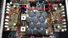
There is one thing you should change as soon as you can. Remove that stuff around the filter capacitors to allow free air flow. Capacitors do generate heat and you are making them hit higher temperatures like this. Also, if you can, leave more space in between the top and lower sections for the same reason.
Other than that, nice and clean. Active crossovers are the way to go! Good decision for that as well!
-Chris
Nice, but dense.
There is one thing you should change as soon as you can. Remove that stuff around the filter capacitors to allow free air flow. Capacitors do generate heat and you are making them hit higher temperatures like this. Also, if you can, leave more space in between the top and lower sections for the same reason.
Other than that, nice and clean. Active crossovers are the way to go! Good decision for that as well!
-Chris
That 'stuff' appears to be hot wax/glue. Presumably to help damp the capacitors?Hi ioannidis,
Nice, but dense.
There is one thing you should change as soon as you can. Remove that stuff around the filter capacitors to allow free air flow. Capacitors do generate heat and you are making them hit higher temperatures like this. Also, if you can, leave more space in between the top and lower sections for the same reason.
Other than that, nice and clean. Active crossovers are the way to go! Good decision for that as well!
-Chris
Hi ioannidis,
Well, you don't need the damping as much as you need the air flow.
If you miss an oil change, the engine doesn't seize immediately. However, it will get you in the long run. Component temperature is the one thing you have to keep as low as reasonably possible. So don't do anything that raises the case temperature - given a choice.
Here's a stat for you. Failure rate doubles for each 10 °C rise in temperature. In your case, the capacitors will simply be old before their time, reducing the sound quality slowly over time. Outright failure is dramatic, but doing what you have opposes high quality construction. Just saying since this is easy to rectify.
-Chris
now i will work on my speakers to remove the passive crossovers.
Hopefully your passive crossover is not good enough. So you wouldn't have to worry about dumping your active crossover and put the passive crossover back on
You know, Magnesium cone naturally wont have a smooth frequency response. And it is not easy to make it smooth using active crossover. May be you want to use passive notch filter, I don't know. Let us know how you deal with it
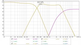
no, i have built those speakers by myself. The active crossover is designed using LEAP software and using the frequency response curves of each driver, so in simulation the response looks fine to me. the crossover is 24db/oct in all sections so the magnesium cone problems are not in the useful range. the cross frequencies are 300 and 3khz.
below is the real measured frequency response of the crossover.
below is the real measured frequency response of the crossover.
Attachments
Last edited:
i just measured the wattage drawn by the amplifier when is on idle or playing music low. it is 300w. I expected this number because i was running for several years two channel version of this amp and it was about 100w idle.
the heatsinks are hot and you barely can touch them. The idle current is about 90-100ma per mosfet and there are 24 on each heatsink.
the heatsinks are hot and you barely can touch them.
The idle current is about 90-100ma per mosfet and there are 24 on each heatsink.
Last edited:
- Home
- Amplifiers
- Solid State
- Post your Solid State pics here