Hi Denis,
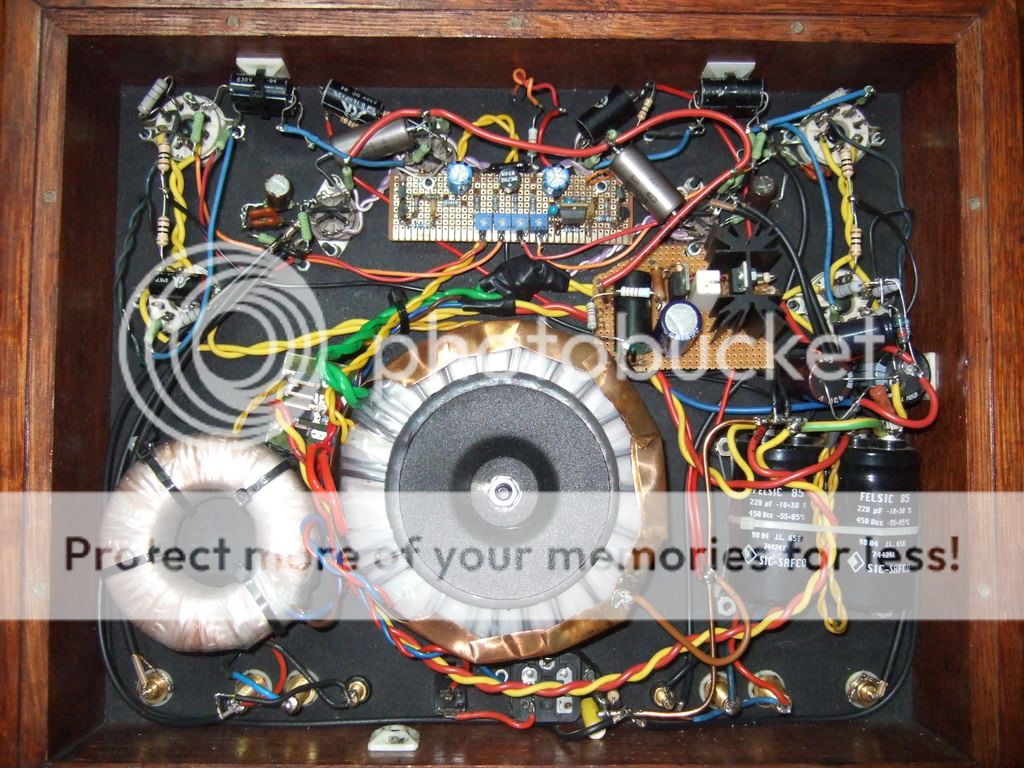
Is a highly modified version of Rockna RD2.
http://www.audiokit.ro/cart/index.php?productID=118
DSD1792 instead of PCM1796 and modified i/v stage to cope with new DAC
Toshiba low Cob output devices at high idle current (single ended output)
Low noise shunt regulator for clock CXO, separated for other digital circuits.
OSCONs and silvered mica in key positions
Low radiation r-core trafo for analog stages.
CRCRC power supply in front of CCS+shunt onboard regulators for I/V stages.
and many many other small but important changes")
Cheers,
Mihai
Is a highly modified version of Rockna RD2.
http://www.audiokit.ro/cart/index.php?productID=118
DSD1792 instead of PCM1796 and modified i/v stage to cope with new DAC
Toshiba low Cob output devices at high idle current (single ended output)
Low noise shunt regulator for clock CXO, separated for other digital circuits.
OSCONs and silvered mica in key positions
Low radiation r-core trafo for analog stages.
CRCRC power supply in front of CCS+shunt onboard regulators for I/V stages.
and many many other small but important changes
Cheers,
Mihai


Wow....
Good job.
Rcore transfo are they the same type of "split type' ? http://media.digikey.com/photos/Tamura Photos/3FL34-170.jpg
Good job.
Rcore transfo are they the same type of "split type' ? http://media.digikey.com/photos/Tamura Photos/3FL34-170.jpg
Re: Why a carefully designed project can fail.
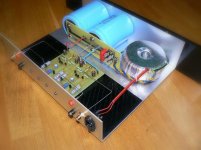
I have solved toroid field induced buzz this way. Try it.
Sorry its a tube amp, non related to a solid state posting place, but the earthed copper sleeve works in any sensitive environment.
fotios said:there are some unexpected bad results.
I have solved toroid field induced buzz this way. Try it.
Sorry its a tube amp, non related to a solid state posting place, but the earthed copper sleeve works in any sensitive environment.
DRZ1 said:Wow....
Good job.
Rcore transfo are they the same type of "split type' ? http://media.digikey.com/photos/Tamura Photos/3FL34-170.jpg
No, that's an E-I type split bobbin. Those are the ones I use for low power applications. Good, but not as good as the R-core.
Re: Re: Why a carefully designed project can fail.
Thanks Salas for the assistance.
I tried already this solution with copper foil of 0,5mm thick arround toroid (which is made in Giatras - 500VA encapsulated = 75 euros), but... nothing. Cables are comming from the bottom of toroid thus for mounting it a sub-chassis is neccessary. I have made a plate from 3mm thick alu of 145mm width (which is exactly the diameter of x-former) which is joined between the front and back pannel. The mistake was clearly mine: I trusted Giatras for this custom ordered "supposevelly super low noise" toroid. Bearing in mind this, i designed the whole amplifier. I got my lesson. The only cure exists, it is the redrawing of amp pcbs so as can placed on heatsinks thus vertically in relation with toroid and FAR AWAY from it.
BTW, take a look in the DAC project of "roender" to get an idea how is placed the R type xformer of Selectronic which is absolute noiseless (i have tried one 500VA before 1 year).
Regs
Fotios
salas said:
I have solved toroid field induced buzz this way. Try it.
Sorry its a tube amp, non related to a solid state posting place, but the earthed copper sleeve works in any sensitive environment.
Thanks Salas for the assistance.
I tried already this solution with copper foil of 0,5mm thick arround toroid (which is made in Giatras - 500VA encapsulated = 75 euros), but... nothing. Cables are comming from the bottom of toroid thus for mounting it a sub-chassis is neccessary. I have made a plate from 3mm thick alu of 145mm width (which is exactly the diameter of x-former) which is joined between the front and back pannel. The mistake was clearly mine: I trusted Giatras for this custom ordered "supposevelly super low noise" toroid. Bearing in mind this, i designed the whole amplifier. I got my lesson. The only cure exists, it is the redrawing of amp pcbs so as can placed on heatsinks thus vertically in relation with toroid and FAR AWAY from it.
BTW, take a look in the DAC project of "roender" to get an idea how is placed the R type xformer of Selectronic which is absolute noiseless (i have tried one 500VA before 1 year).
Regs
Fotios
jwb said:No, that's an E-I type split bobbin.
The Tamura transformer doesn't have an E (laminate).

It's a semi-toroidal U-I.
Re: Re: Re: Why a carefully designed project can fail.
Sorry to hear that. Seems like a lot of nice work to get spoiled by the trafo.
fotios said:
Thanks Salas for the assistance.
I tried already this solution with copper foil of 0,5mm thick arround toroid (which is made in Giatras - 500VA encapsulated = 75 euros), but... nothing. Cables are comming from the bottom of toroid thus for mounting it a sub-chassis is neccessary. I have made a plate from 3mm thick alu of 145mm width (which is exactly the diameter of x-former) which is joined between the front and back pannel. The mistake was clearly mine: I trusted Giatras for this custom ordered "supposevelly super low noise" toroid. Bearing in mind this, i designed the whole amplifier. I got my lesson. The only cure exists, it is the redrawing of amp pcbs so as can placed on heatsinks thus vertically in relation with toroid and FAR AWAY from it.
BTW, take a look in the DAC project of "roender" to get an idea how is placed the R type xformer of Selectronic which is absolute noiseless (i have tried one 500VA before 1 year).
Regs
Fotios
Sorry to hear that. Seems like a lot of nice work to get spoiled by the trafo.
P.S. On that amplifier pic I posted with the DIY copper circumferential grounded sleeve, the main buzz pick up lines were the input stage ground returns to the buss bar that were very near the trafo. 90% of the problem I solved by using shielded coaxial for them with only one end of the shield connected to the ground bar. The last 10% to total silence on 95dB speakers, was the toroid added copper sleeve. Maybe you can use that method too for the wires that run under your toroid?
Re: Re: AMB Laboratories' ?4: A discrete, cascoded, fully-differential power amplifier
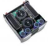
No, they're 625VA toroidal transformers, an overkill.
Moreover, there is a 100VA toroidal transformer for the front end on each side of the heatsinks in the front. Altogether I have 4 transformers in the case.
fotios said:
Hmmm....
Good work in general... But i must to point out, the right choice and orientation of toroidal xformers. You are using instead one monster of, say, 500VA two of 250VA. That means less magnetizing current and consequently less radiation of magnetic flux arround. The second is the vertical mounting of toroids related to orientation of pcbs. This ensures that the magnetic flux radiated from toroids, can't affect the noise sensitive stages of amplifier boards. This amplifier must be very quiet without buzz or crackling noise assuming that the star point of gnd nodes has been done correctly, so there are not gnd loops.
Bravo housing
Fotios
No, they're 625VA toroidal transformers, an overkill.
Moreover, there is a 100VA toroidal transformer for the front end on each side of the heatsinks in the front. Altogether I have 4 transformers in the case.
jacco vermeulen said:Aaah, the Beta24 (fuggin Firefox doesn't show me the Beta sign)
Very smart feedback operation in that design.
Yes, it is.
gerhard said:Next generation of the low noise preamp of post 671.
Gain = 0 / 60 / 80 dB, Bandwidth > 1 MHz
first stage this time 3 pairs of SSM2210, then AD797
for a gain of 60 dB, another 797 for another 20 dB,
1/2 BB/TI opa2134 for offset correction loop, the other half
serves as a follower for 0 dB gain.
Gain is switched with bistable relays to avoid offset wander
when a relay is energized.
Power supplies are filtered with capacitance multipliers.
Signal connectors are SMA, the round connector is for
power and relay coils.
The important resistors are Susumu thin film 0.1 or 0.5 %.
regards, Gerhard
Congratulations Gerhard, really proffesional work there. I would love to see the schematics. I also use SSM2210/2220 in my amps and I got better noise results in comparison with MAT02/03. Strange since the last ones are housed in a metal case.
salas said:I mean wrapping some copper tape around them and grounding it in your case. Most of the erratic field is radiated from the secondary exits and the cables themselves in my experience.
But that is just as bad with an EI core as with a toroid. Flux encirling the secondary exits will be the same in either case - but you're not as likely to put them close to the inputs/feedback with an EI trafo.
I've had secondary exits indcung hum into the input stages of an adjacent amplifier. The hum got worse in the amp on the bottom the harder the top amp in the rack was pushed. They were EI core.
wg_ski said:
But that is just as bad with an EI core as with a toroid. Flux encirling the secondary exits will be the same in either case - but you're not as likely to put them close to the inputs/feedback with an EI trafo.
I've had secondary exits indcung hum into the input stages of an adjacent amplifier. The hum got worse in the amp on the bottom the harder the top amp in the rack was pushed. They were EI core.
Hum noise caused from electromagnetic flux (Ö) radiated from the core of transformer in any direction. Of course its stronger part radiated in the same direction as it flows in the core. Another one source that can cause hum noise, it is a high magnetizing current... e.g. if the core of toroid is made from single steel band which has 6 times less magnetic permeability (ì) from electric steel (please see in wikipedia for details) then it needs 6 times more current to magnetized to produce the appropriate "Ö". An ideal core, could be made from Mu-metal, which presents the higher "ì" but its price is prohibitive. Electric steel is the usual alloy of cores and has 5 times less "ì" from Mu-metal.
A good core "Ö" shielding can be done only from alloys with high "ì" because only these can absorbe "Ö". Copper and Alu have 700 times less "ì" from steel and 4000 times from electric steel. Thus in practice they can't offer any good shielding except than have enormous thicknes. It is prefferable the use of electric steel for "Ö" shielding.
Permalloy is the second alloy in the table of "ì" and has 2 times bigger "ì" from electrical steel. It is less expensive from Mu-metal, and there are laminates from permalloy for constructing EI xformers for very sensitive measuring instruments like medicals. Of course in audio power xformers its cost is prohibitive.
The vast majority of toroid xformer constructors, they based on the shielding of core by the copper windings, in the momment that copper offers the same "Ö" absorption like water. Alu, Copper, water, vacuum have the same low "ì". Also, they do a second mistake which is the tightening of the spiral formed core from the copper windings. How much strain force can accept a thin copper wire?
IMHO a good core must be formed very tightly, and dipped in a bath of epoxy varnish under vacuum to become still like a rock. The same make the good constructors of EI xformers. Thus any mechanical noise will be minimized. After the core has dried thoroughly, the primary winding can be done. After, a bath again in epoxy varnish it is good. After insulating the primary winding with (usually) mylar tape, an auxiliary internal belly band from copper tape it is good. A terminal wire soldered on this belly band it is appropriate to earthed later. Above the internal belly band, a second winding from mylar tape it is indispensable for insulation. Now it is time for the secondary winding. After its completion, again a bath in epoxy varnish it is good. Then it follows the insulation of the secondary winding with mylar tape. Now we have a toroid with the ordinary appearance. At this point, an external belly band around the circumference of toroid from electrical steel, can offer a good absorption of "Ö" radiated from core. Alu and copper thin foils, are good conductors of "Ö", consequently are useless. Instead a bowl made from 8-10mm thick Alu, can be a good screen. If we have a such made transformer, we can place it near and in any direction with the sensitive pcbs.
In different case, the only that we can do, it is the place of sensitive pcbs vertically in relation with the circumference of toroid... and as far as possible from it.
Mechanical noise is a negligible part of hum noise injected in the audio path. The 99% of hum noise is caused from "Ö". Top and bottom covers of amplifier case, they share the "Ö" of xformer generated in unpredictable directions inside the case... like mirrors or transmitters (i don't know exactly).
A good example of pcbs orientation in relation with xformers, appears in the attached picture of a Mark Levinson.
Attachments
- Home
- Amplifiers
- Solid State
- Post your Solid State pics here