
dirty harry
hi fotios
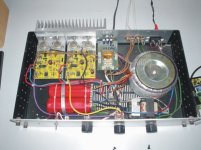
greetings i have posted picture of heat sink along with pcb
driver transistors are on aluminium heatsink along with mje 340
can you give voltage of transistors
1 what is the value of preset 500 ohms or 5 k ohms
2 using mj15023 15024 as driver transistor is it okay
3 how did you set quiescnt current
thank you fotios for the encouragement waiting to hear from you
thanking you
andrew lebon
hi fotios
greetings i have posted picture of heat sink along with pcb
driver transistors are on aluminium heatsink along with mje 340
can you give voltage of transistors
1 what is the value of preset 500 ohms or 5 k ohms
2 using mj15023 15024 as driver transistor is it okay
3 how did you set quiescnt current
thank you fotios for the encouragement waiting to hear from you
thanking you
andrew lebon
Re: dirty harry
Hi Andrew
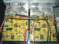
I am very sorry for that: You have did a serious mistake... you have mount the output transistors in seperate heatsinks, in one the PNP and in other the NPN.
And now how can track the Vbe multiplier the temp variation of output transistors to compensate the iddle current?
Please send me a bigger picture with e-mail, and go back in the original thread for the rest.
Fotios
andrewlebon said:hi fotios
greetings i have posted picture of heat sink along with pcb
driver transistors are on aluminium heatsink along with mje 340
can you give voltage of transistors
1 what is the value of preset 500 ohms or 5 k ohms
2 using mj15023 15024 as driver transistor is it okay
3 how did you set quiescnt current
thank you fotios for the encouragement waiting to hear from you
thanking you
andrew lebon
Hi Andrew
I am very sorry for that: You have did a serious mistake... you have mount the output transistors in seperate heatsinks, in one the PNP and in other the NPN.
And now how can track the Vbe multiplier the temp variation of output transistors to compensate the iddle current?
Please send me a bigger picture with e-mail, and go back in the original thread for the rest.
Fotios
Re: Re: dirty harry
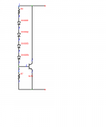
Yes, this is a mistake and it will cause thermal runaway. But there is a fix. I've had to build lots of big amps that needed the NPNs and PNPs on separate heatsinks - mostly due to physical constaints of building with what's available. The Leach-type Vbe multiplier works like a charm in those cases. Just mount two of the diodes one one sink, two on the other, and the multiplier transistor itself near the predrivers. For the "diodes" the easiest implementation is a diode-connected transistor in one of those fully-encapsulated cases (like a BD139). Of course, the upper resistor value needs adjustment - will need to be approximately the same as the base-emitter resistor value.
fotios said:
You have did a serious mistake... you have mount the output transistors in seperate heatsinks, in one the PNP and in other the NPN.
And now how can track the Vbe multiplier the temp variation of output transistors to compensate the iddle current?
Fotios
Yes, this is a mistake and it will cause thermal runaway. But there is a fix. I've had to build lots of big amps that needed the NPNs and PNPs on separate heatsinks - mostly due to physical constaints of building with what's available. The Leach-type Vbe multiplier works like a charm in those cases. Just mount two of the diodes one one sink, two on the other, and the multiplier transistor itself near the predrivers. For the "diodes" the easiest implementation is a diode-connected transistor in one of those fully-encapsulated cases (like a BD139). Of course, the upper resistor value needs adjustment - will need to be approximately the same as the base-emitter resistor value.
Attachments
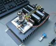
And this is one implementation that needed it - badly. There is a second heatsink under the one you can see. One bank is NPN, one PNP. With one Vbe multiplier, it ran away in about 2 hours. When revised, I put one diode on one NPN output transistor (directly), one on a PNP, and one on the NPN driver and one on the PNP. No more runaway. This thing drives two labhorns (in parallel) for 2 ohms.
Attachments
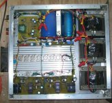
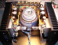
Case is made the same way all of mine are. 0.125 or 0.090 sheet aluminum stock, cut into panels. Bolted together with angle aluminum. This particular series used a perfab 3U steel rack panel for the fronts - and yes, the trafos are bolted to the front panel.
Output trannies are the MJ21193/4. There's a total of 20 plus drivers. There are two heat sinks stacked on top of one another, with the 4" 105CFM fan blowing through them. Exhaust holes are in the top of the case. The circuit is posted in the "700 watt amplifier" thread, which is buried somewhere by now, and brought up again recently when another member got interested in Project 117. As you can see, this similar amp is finished and has been working in the field for some time.
Output trannies are the MJ21193/4. There's a total of 20 plus drivers. There are two heat sinks stacked on top of one another, with the 4" 105CFM fan blowing through them. Exhaust holes are in the top of the case. The circuit is posted in the "700 watt amplifier" thread, which is buried somewhere by now, and brought up again recently when another member got interested in Project 117. As you can see, this similar amp is finished and has been working in the field for some time.
The "Dimitra" Amplifier...
Hallo to everybody !
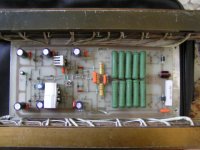
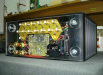
..this is my realization of a PtP n-hexfet stereo amp ("The Saint" 's design.. thanks man.!) with 1 pair of industrial 60Amp peak current fets & ecc83 triode buffer per channel, @ +/-33v rails, fused protection, soft start delay, descrete geared attenuator pots, a balance pot (hi-fi style) & 6 input selector+rec out, hand made to the bone.
Hallo to everybody !
..this is my realization of a PtP n-hexfet stereo amp ("The Saint" 's design.. thanks man.!) with 1 pair of industrial 60Amp peak current fets & ecc83 triode buffer per channel, @ +/-33v rails, fused protection, soft start delay, descrete geared attenuator pots, a balance pot (hi-fi style) & 6 input selector+rec out, hand made to the bone.
Attachments
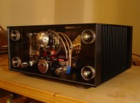
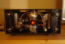
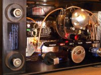
..ok just one more.. the one i call 'train engine'..
..it sounds great .. the detail through my diy ecl's is spectacular, sweet, tube like sound & distortion at hi levels, no hot spots inside so ventilation holes ,no pcb except for holding the caps & rectifiers...
..it sounds great .. the detail through my diy ecl's is spectacular, sweet, tube like sound & distortion at hi levels, no hot spots inside so ventilation holes ,no pcb except for holding the caps & rectifiers...
Attachments
- Home
- Amplifiers
- Solid State
- Post your Solid State pics here