tmyr: 
I am also building tube pre-amp w/solid state output amps for musical instruments and microphones. ... (Hybrid Amps = The latest is using 12AX7 front end kits to MOSFET power modules from various manufacturers, mostly The Saint's designs and products, but soon will try tube front ends of my own design. These are limited to 200 and 400 watts per channel, so far ...)
Great concept, great pictures ... more please!
Re: The "Dimitra" Amplifier...

That is one of the coolest things I have ever seen! I especially like the knobs.
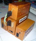
tmyr said:Hallo to everybody !
..this is my realization of a PtP n-hexfet stereo amp
That is one of the coolest things I have ever seen! I especially like the knobs.
..thank you friends for yor kind words !
..i tell u, this ptp style is great fun.. you should try this !
its like a 3d puzzle and can keep you ocupied for quite some time to build it (second unit was much quicker since u copy what u see), but with a good architectural placement of components you can get the smollllest possible (with minor compromises) distance between them and a pleasing+interesting ressult to the eye. but most interesting was to observe the diferense between pcb and good ptp and found that there IS a difference. i even found a commercialist hi-ender 's web page advertizing this technique with words full of flowers and butterflies, and imagine he did this to a chip amp! ..imply this (i heard it is called the "dead bug" technique) to a good clean prooven descrete schematic like "The Saint" 's n-channel amp and you will at least have something ..unusual in your amps collection.. coffee does not help here very much  ..my result is practicaly noise free despite the toroids proximity and very musical to my ears, a young piano player friend gave me a 90% reality to the piano (and found the crossover dips in my setup!!!)
..through esl's at late night hearings the detail has really impressed me so far and has quite a punch for a small party ..!
(please excuse my spelling errors)
..i tell u, this ptp style is great fun.. you should try this !
its like a 3d puzzle and can keep you ocupied for quite some time to build it (second unit was much quicker since u copy what u see), but with a good architectural placement of components you can get the smollllest possible (with minor compromises) distance between them and a pleasing+interesting ressult to the eye. but most interesting was to observe the diferense between pcb and good ptp and found that there IS a difference. i even found a commercialist hi-ender 's web page advertizing this technique with words full of flowers and butterflies, and imagine he did this to a chip amp! ..imply this (i heard it is called the "dead bug" technique) to a good clean prooven descrete schematic like "The Saint" 's n-channel amp and you will at least have something ..unusual in your amps collection..
coffee does not help here very much ..my result is practicaly noise free despite the toroids proximity and very musical to my ears, a young piano player friend gave me a 90% reality to the piano (and found the crossover dips in my setup!!!)..through esl's at late night hearings the detail has really impressed me so far and has quite a punch for a small party ..!
(please excuse my spelling errors)
Attachments
Audio Analogue Maestro
I still have this amp. I am waiting for the factory to send new circuit PCBs. I am not really looking forward to removing all the power supply wires from 2 transformers to make the replacement.
My file was too large, now its 84K in jpeg format. Do not know why it will not import.
I still have this amp. I am waiting for the factory to send new circuit PCBs. I am not really looking forward to removing all the power supply wires from 2 transformers to make the replacement.
My file was too large, now its 84K in jpeg format. Do not know why it will not import.
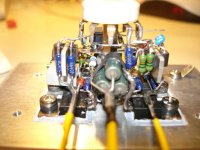
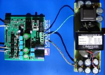
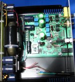
Next generation of the low noise preamp of post 671.
Gain = 0 / 60 / 80 dB, Bandwidth > 1 MHz
first stage this time 3 pairs of SSM2210, then AD797
for a gain of 60 dB, another 797 for another 20 dB,
1/2 BB/TI opa2134 for offset correction loop, the other half
serves as a follower for 0 dB gain.
Gain is switched with bistable relays to avoid offset wander
when a relay is energized.
Power supplies are filtered with capacitance multipliers.
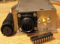
Signal connectors are SMA, the round connector is for
power and relay coils.
The important resistors are Susumu thin film 0.1 or 0.5 %.
regards, Gerhard
Gain = 0 / 60 / 80 dB, Bandwidth > 1 MHz
first stage this time 3 pairs of SSM2210, then AD797
for a gain of 60 dB, another 797 for another 20 dB,
1/2 BB/TI opa2134 for offset correction loop, the other half
serves as a follower for 0 dB gain.
Gain is switched with bistable relays to avoid offset wander
when a relay is energized.
Power supplies are filtered with capacitance multipliers.
Signal connectors are SMA, the round connector is for
power and relay coils.
The important resistors are Susumu thin film 0.1 or 0.5 %.
regards, Gerhard
Attachments
Bravo Gerhard
Excellent work. Don't say me that the case of your pre except die cast it is also made from "mumetal" because i will faint!
BTW your construction it is a very good lesson about cases. The 99,9% of cases are constructed from 6 plates, two for top and bottom covers, two for side covers (which in amps are usually heatsinks) and two for front and back panels. We have thus, already formed 8 capacitors from the plates... if we add also the screws needed for assembling the case, we must multiply the 8 by the number of screws used to we get the final number of capacitors exists arround the electronic circuit found inside the case.
For this reason circuits with big sensitivity must closed inside die cast cases. You know probably "mumetal" from which are made the covers of input - output coupling transformers. Mumetal is the only absorbing alloy of electromagnetic flux.
As for xformers, be it so toroids with the least flux radiated arround, the better are dipped in alu die cast bowl with epoxy rosin. Alu it does not absorb flux, but not conduct it, simply operates such a mirror.
Regs
Fotios
Re: AMB Laboratories' â24: A discrete, cascoded, fully-differential power amplifier
Hmmm....
Good work in general... But i must to point out, the right choice and orientation of toroidal xformers. You are using instead one monster of, say, 500VA two of 250VA. That means less magnetizing current and consequently less radiation of magnetic flux arround. The second is the vertical mounting of toroids related to orientation of pcbs. This ensures that the magnetic flux radiated from toroids, can't affect the noise sensitive stages of amplifier boards. This amplifier must be very quiet without buzz or crackling noise assuming that the star point of gnd nodes has been done correctly, so there are not gnd loops.
Bravo housing
Fotios
housing said:AMB Laboratories' â24: A discrete, cascoded, fully-differential power amplifier
Freshly brewed.
Hmmm....
Good work in general... But i must to point out, the right choice and orientation of toroidal xformers. You are using instead one monster of, say, 500VA two of 250VA. That means less magnetizing current and consequently less radiation of magnetic flux arround. The second is the vertical mounting of toroids related to orientation of pcbs. This ensures that the magnetic flux radiated from toroids, can't affect the noise sensitive stages of amplifier boards. This amplifier must be very quiet without buzz or crackling noise assuming that the star point of gnd nodes has been done correctly, so there are not gnd loops.
Bravo housing
Fotios
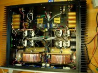
Why a carefully designed project can fail.
In the picture bellow you can see the project implemented. It is a class AB power amplifier of 2 X 180Wrms/8Ù in dual mono arrangement. Although the first impression can bee: WOW! what a nice construction fotios; there are some unexpected bad results.
The main problem is the presense of buzz (or crackling) noise, be it so very small of 1,2mVrms, in output. Under normal listening conditions it is unaudible except if you stick your ear on the cone of woofer under absolute silence... because i am strange man and i have the habbit to test a finished project for a couple of days as much, i am interested mainly for the performance. I haven't time to enjoy with my constructions. Thus my thought it is clearly of mechanical way.
According this, the only acceptable noise in output must be only a little hiss caused from the electronic parts. It is a painfull work to obtain someone a noiseless project which have a Av=43, in conjuction with easiness in repair work. An easy repair work can be obtained only if the amp. pcbs are accessible directly when the bottom cover is removed. The difficult way is when the pcbs are mounted parallel on heatsink thus vertically related to xformer position. In this amplifier on the picture, the amp pcbs are mounted vertically on heatsink and alongside with the xformer. The result is that the sensitive input stages of the two channels are infected from a straight magnetic flux radiated from the 500VA toroidal xformer. Don't be deceived by the supposed immunity of transformer with the bowl, because it is from steel. Steel it is a good conductor of magnetic flux, thus the steel bowl is uselless. The only cure, it is the mounting of pcbs parallel on heatsinks. I hate this thing, for the reasons mentioned above. I can't turn the xformer vertically because its 14,5cm diameter, instead the height of amplifier is 10cm.
Let's go now to the subject called toroid xformer. Before one year, i had not so many knoweledge about this kind of xformers because i used EI type xformers. Toroids are in the round about 25 years. Theoretically, are less noisy from EI xformers. From the other hand, EI xformers have a technological and historical background of enough decades ago. In comparison, toroids are yet IMHO "tabula rasa". In my career, i don't remember to have seen inside a measuring instrument (included medicals) a toroid xformer for power supply. I have seen only EI xformers of different shapes, with double belly bands electricaly earthed and in many cases covered with nickel plate (or mumetal). This make sense. After enough searching, i resulted in this: very few constructors arround the world can build correctly a toroid. Do you now that, the famous Plitron in their LoNo series toroids make use of a belly band from copper tape (earthed) between primary and secondary windings? Ha! Where is gone the guaranteed screening formed only from the copper windings of toroid, as reffered in wikipedia? Why the need for cylidrical covers from special alloys? Aluminium by alone it is not enough! Mumetal it is prohibitivelly expensive. The big secret it is the alloy of the spiral core. The higher the magnetic permeability ( ì ) of alloy, the less the magnetizing current thus the less magnetic flux radiated. Constructors usually make use of a steel - Fe band to form the core. Fe has a mid to high "ì". The issue it is that, the high magnetizing current cause mechanical noise except mag. flux radiation in a distance arround 3 to 4cm from the circumference of a toroid.
As for EI xformers, today offered a variety of alloys from which are constructed their E and I laminates. Double belly bands earthed offers a good screening. As for mechanical noise, NO! EI xformers are "open" after their completion for a good impregnation with epoxy varnish into a vacuum can. After 2 - 3 days, when the varnish dried thoroughly, the laminates are sticked between them and the core becomes still like a rock.
I have read somewhere a report of N. Pass about a Plitron toroid: "With a stethoscope, we could hear a little noise from the core of transformer"...
And i am wondering. Are toroids for causing impression? An EI xformer it is not "a must" inside a Hi-End amplifier?
For me, either of the two types is equally good, but only and only if it is constructed correctly!
BTW, in Greece there is a laboratory of EI xformers which can produce top grade xformers, yet for the bigger demand you can imagine. For toroids... a lot of labs operated from "proffesional" amateurs.
Fotios
In the picture bellow you can see the project implemented. It is a class AB power amplifier of 2 X 180Wrms/8Ù in dual mono arrangement. Although the first impression can bee: WOW! what a nice construction fotios; there are some unexpected bad results.
An externally hosted image should be here but it was not working when we last tested it.
The main problem is the presense of buzz (or crackling) noise, be it so very small of 1,2mVrms, in output. Under normal listening conditions it is unaudible except if you stick your ear on the cone of woofer under absolute silence... because i am strange man and i have the habbit to test a finished project for a couple of days as much, i am interested mainly for the performance. I haven't time to enjoy with my constructions. Thus my thought it is clearly of mechanical way.
According this, the only acceptable noise in output must be only a little hiss caused from the electronic parts. It is a painfull work to obtain someone a noiseless project which have a Av=43, in conjuction with easiness in repair work. An easy repair work can be obtained only if the amp. pcbs are accessible directly when the bottom cover is removed. The difficult way is when the pcbs are mounted parallel on heatsink thus vertically related to xformer position. In this amplifier on the picture, the amp pcbs are mounted vertically on heatsink and alongside with the xformer. The result is that the sensitive input stages of the two channels are infected from a straight magnetic flux radiated from the 500VA toroidal xformer. Don't be deceived by the supposed immunity of transformer with the bowl, because it is from steel. Steel it is a good conductor of magnetic flux, thus the steel bowl is uselless. The only cure, it is the mounting of pcbs parallel on heatsinks. I hate this thing, for the reasons mentioned above. I can't turn the xformer vertically because its 14,5cm diameter, instead the height of amplifier is 10cm.
Let's go now to the subject called toroid xformer. Before one year, i had not so many knoweledge about this kind of xformers because i used EI type xformers. Toroids are in the round about 25 years. Theoretically, are less noisy from EI xformers. From the other hand, EI xformers have a technological and historical background of enough decades ago. In comparison, toroids are yet IMHO "tabula rasa". In my career, i don't remember to have seen inside a measuring instrument (included medicals) a toroid xformer for power supply. I have seen only EI xformers of different shapes, with double belly bands electricaly earthed and in many cases covered with nickel plate (or mumetal). This make sense. After enough searching, i resulted in this: very few constructors arround the world can build correctly a toroid. Do you now that, the famous Plitron in their LoNo series toroids make use of a belly band from copper tape (earthed) between primary and secondary windings? Ha! Where is gone the guaranteed screening formed only from the copper windings of toroid, as reffered in wikipedia? Why the need for cylidrical covers from special alloys? Aluminium by alone it is not enough! Mumetal it is prohibitivelly expensive. The big secret it is the alloy of the spiral core. The higher the magnetic permeability ( ì ) of alloy, the less the magnetizing current thus the less magnetic flux radiated. Constructors usually make use of a steel - Fe band to form the core. Fe has a mid to high "ì". The issue it is that, the high magnetizing current cause mechanical noise except mag. flux radiation in a distance arround 3 to 4cm from the circumference of a toroid.
As for EI xformers, today offered a variety of alloys from which are constructed their E and I laminates. Double belly bands earthed offers a good screening. As for mechanical noise, NO! EI xformers are "open" after their completion for a good impregnation with epoxy varnish into a vacuum can. After 2 - 3 days, when the varnish dried thoroughly, the laminates are sticked between them and the core becomes still like a rock.
I have read somewhere a report of N. Pass about a Plitron toroid: "With a stethoscope, we could hear a little noise from the core of transformer"...
And i am wondering. Are toroids for causing impression? An EI xformer it is not "a must" inside a Hi-End amplifier?
For me, either of the two types is equally good, but only and only if it is constructed correctly!
BTW, in Greece there is a laboratory of EI xformers which can produce top grade xformers, yet for the bigger demand you can imagine. For toroids... a lot of labs operated from "proffesional" amateurs.
Fotios
Re: Re: AMB Laboratories' â24: A discrete, cascoded, fully-differential power amplifier
Fotios, thanks for all the kind words.
Yes, the power amp is dead quiet by design and layout. It's a balanced amp.
fotios said:
Hmmm....
Good work in general... But i must to point out, the right choice and orientation of toroidal xformers. You are using instead one monster of, say, 500VA two of 250VA. That means less magnetizing current and consequently less radiation of magnetic flux arround. The second is the vertical mounting of toroids related to orientation of pcbs. This ensures that the magnetic flux radiated from toroids, can't affect the noise sensitive stages of amplifier boards. This amplifier must be very quiet without buzz or crackling noise assuming that the star point of gnd nodes has been done correctly, so there are not gnd loops.
Bravo housing
Fotios
Fotios, thanks for all the kind words.
Yes, the power amp is dead quiet by design and layout. It's a balanced amp.
Bonsai said:"In the picture bellow you can see the project implemented."
fotios, is this one of your projects? Can we se e some mor e pictures?
Looks very good
Thanks to my respectable on-line friend Bonsai, i can post as many pictures you want. Because the batteries of my camera must be recharged, i ask your patience for one day.
Also, if you wish, drop me a link to send you schematics etc.
Yes, it is at whole my own design including an error analog computer for any possible abuse of amplifier, a very simple soft start circuit (arround a Rhopoint SurgeGard ntc), error leds, and two balanced to single ended converters implemented with smd discrettes on the back plate.
Fotios
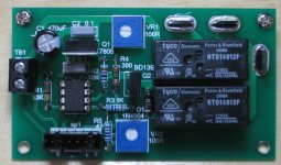
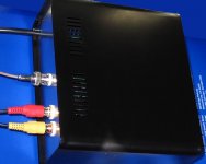
Here is my latest "add-on". A simple, but effective and high quality A/B speaker switch. I used an 8 pin PIC12F675 to do everything - debounce the momentary switch, drive the LEDs and drive the relay. Simple software.
The relays are 12V coil 250V/16A each, paralleled for extra capacity. I was going to use latching relays, but couldn't find really suitable ones, so in the end used Potter & Brumfield RTD14012F. The boards measure 85x50mm and one board is used for each channel.
The relays are 12V coil 250V/16A each, paralleled for extra capacity. I was going to use latching relays, but couldn't find really suitable ones, so in the end used Potter & Brumfield RTD14012F. The boards measure 85x50mm and one board is used for each channel.
Attachments
- Home
- Amplifiers
- Solid State
- Post your Solid State pics here