Hi OS
The power supply on the Genesis amp would suit the nxv300 or the nxv500 modules.
The NXV series is quite different in the topology from the AV400 amp.
As good as the AV400 was it is not as nearly as good as the NXV300 or NXV500 amplifier modules.
Both in Objective and Subjective performance.
Current pricing on the nxv300 module is $196.00USD each
and the nxv500 is $267.00USD each.
If you are looking at more than 4 units please email me at aussieamps@gmail.com and I can offer you better deal.
I hope this helps")
The power supply on the Genesis amp would suit the nxv300 or the nxv500 modules.
The NXV series is quite different in the topology from the AV400 amp.
As good as the AV400 was it is not as nearly as good as the NXV300 or NXV500 amplifier modules.
Both in Objective and Subjective performance.
Current pricing on the nxv300 module is $196.00USD each
and the nxv500 is $267.00USD each.
If you are looking at more than 4 units please email me at aussieamps@gmail.com and I can offer you better deal.
I hope this helps
Saint: Is it a voltage question above with the "huge 160 lb amps" ?
(I have trouble IDing the proper xformers and voltages required or recommended for some of your boards.)
Personally, I would use the NXV500 modules for ostripper's "huge amp" above. Mostly 'cause the '500's will never get hot on those massive sinks, no way, no how, if properly feed by a the right xformer (voltage & volt/amp wise).
FYI: my "old" NX400 modules are now feed by a bigger donut, 450 VA (Watt) xformer ... and they run even cooler in Nelson Pass's great chassis (quieter too!) ... pics to follow.
FastEddy said:Saint: Is it a voltage question above with the "huge 160 lb amps" ?
(I have trouble IDing the proper xformers and voltages required or recommended for some of your boards.)
Personally, I would use the NXV500 modules for ostripper's "huge amp" above. Mostly 'cause the '500's will never get hot on those massive sinks, no way, no how, if properly feed by a the right xformer (voltage & volt/amp wise).
Hi Ed
I guess the main thing to remember with these Genesis amps is the power supplies are very big and would provide an excellent and very stiff power supply rail for the nxv500 modules and with such large heat sinks, they would have no trouble cooling them. In fact as you have pointed out Ed they would run luke warm, if not quite cold most of the time.
The supply voltage is a bit lower than the nxv500 modules would normally run on at +-78 volts, but it is only going to effect the maximum power output and have no real effect on the overall sound quality.
When you say you are havng trouble Iding the transformers, do you mean finding a suitable local supplier for these transformers?
" ... In fact as you have pointed out Ed they would run luke warm, if not quite cold most of the time. ..."
I have yet to find one of your modules that runs hot ... being class AB power amp (rather than just a voltage amp), they don't pass full power unless you crank 'em way up close to max ... Just 3 db to 6 db down from a clip and they run cool indeed ...
I have yet to find one of your modules that runs hot ... being class AB power amp (rather than just a voltage amp), they don't pass full power unless you crank 'em way up close to max ... Just 3 db to 6 db down from a clip and they run cool indeed ...
" ... and couple of secret modifications ..."
My secrets:
* silver wire on all audio pathways ... between connectors and modules, inbound and outbound from panel controls ... It may not do any good, but it sure does make for interesting conversations.
* Extra caps for PS rail filtering ... plastic (poly type) bypass caps in parallel with PS caps, across the rails to ground and as close to the action as possible, close to the amp / op-amp power pins/connectors/traces. (Ask Bob Pease.)
* Gold plated connectors on the audio pathway and the speaker output. In the interest of economies, only one of a connector pair needs to gold plated. Gold to copper or gold to silver is better than just gold to gold. (Discussion?) If the amp or pre-amp module connections are not gold, then I use gold connectors on the wire side.
* ... more ?
*Silver is better than copper, if you keep it good gauge size, it's also lot more durable in long term.
*filter caps is good to filter high frequency artifacts. Closer means less charge spikes and possible antenna effects
*Good, if you have couple hundred $ buy silver ones, they are a lot better. Depends on your system ability to show details.
*filter caps is good to filter high frequency artifacts. Closer means less charge spikes and possible antenna effects
*Good, if you have couple hundred $ buy silver ones, they are a lot better. Depends on your system ability to show details.
" *filter caps is good to filter high frequency artifacts. Closer means less charge spikes and possible antenna effects ..."
Yes! I usually spec these poly plastic caps at about 1/100 to 1/1000 of the values of the main power supply electrolytic capacitors ... Ex: 20,000 uF electro caps on each PS rail, then plastic bypass caps would be about ~20 uF mounted "close coupled", very close to the power supply pins on the amp modules and/or pre-amp module power supply input points and if possible right across the op-amp pins. Got +/0/- 15 VDC pre-amp rails? Spec the caps to > 35 VDC, two required from negative rail to (signal/power) ground & + rail to (signal/power) ground. (I call this the TI trick, because thats what Texas Inst. and National Semi (and some others) do to get those great specification numbers on their op-amps. In fact TI even explains this in their docs.)
Yes! I usually spec these poly plastic caps at about 1/100 to 1/1000 of the values of the main power supply electrolytic capacitors ... Ex: 20,000 uF electro caps on each PS rail, then plastic bypass caps would be about ~20 uF mounted "close coupled", very close to the power supply pins on the amp modules and/or pre-amp module power supply input points and if possible right across the op-amp pins. Got +/0/- 15 VDC pre-amp rails? Spec the caps to > 35 VDC, two required from negative rail to (signal/power) ground & + rail to (signal/power) ground. (I call this the TI trick, because thats what Texas Inst. and National Semi (and some others) do to get those great specification numbers on their op-amps. In fact TI even explains this in their docs.)
help tp build SS amp
I built a 120w KT88 amp. Now I want to build a SS. Need to.
The wife and I listen to a lot of music, high volume, so the tube amp gets stressed. I have a 300ma choke in the Pwr supply and it gets hot, was a 150ma. Any way, I have an Adcome GFA 555II and we blow fuses on a regular basis.
Paul
I built a 120w KT88 amp. Now I want to build a SS. Need to.
The wife and I listen to a lot of music, high volume, so the tube amp gets stressed. I have a 300ma choke in the Pwr supply and it gets hot, was a 150ma. Any way, I have an Adcome GFA 555II and we blow fuses on a regular basis.
Paul

AUDISOUL said:Hi All,
This all the designs is design by my best Friend, But he dont want to giving this designs to all the guys so sorry and I cant help any body.dont mail me for the designs.He is hurt than I have stop to put his designs here.
In any case, I have not seen anybody that you set such a request; to share the schematics of your projects.
Well, I can't understand the reason; why you wrote the above?
Fotios
Audio Analogue Mono Block
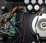
Does anyone have an idea why protection circuit is causing trouble?
The AC main power supply wire goes through an inductor to act as a current sense. This is fed to an opamp circuit that picks up the current as a voltage to a following circuit.
The amp does not turn on consistently with the bias set rather low at 10mV The spec is 30mV, but when the bias is raised to 20+ mV the amp will not turn back on at all.
The gain resistor in the opamp circuit has been lowered, and even the AC main wire removed from inside the inductor. Since the problem persists can I rule out this circuit? Could the AC main wire running next the inductor cause this circuit to still work?. Could it be DC offset? if so, Why would bias effect it?
- Home
- Amplifiers
- Solid State
- Post your Solid State pics here