thanks jacco, i appreciate your advice and opinion.
I personally did read a lot on these past months and i got some handle on the different simulators that i still think be helpfull on building a project.
I got handle on PCB desing and eatching and on some insight on amp design.
I did read Self's book, books on valves which they were really helpfull to understand some concepts.
I'm very glad to be part of this forum and receive usefull advice, they really help.
If you have any suggestion on things that i should learn and study first, i will gladly accept it.
I do recognize the need to learn much more before to be able to post like you and other guys on the forum here do.
Just take in consideration that i'm not completely blank on electronic though , i'm an engineer and i have studied electronic on different course....so i know resistors - capacitor - inductor") ...
...
I look forward ...
I personally did read a lot on these past months and i got some handle on the different simulators that i still think be helpfull on building a project.
I got handle on PCB desing and eatching and on some insight on amp design.
I did read Self's book, books on valves which they were really helpfull to understand some concepts.
I'm very glad to be part of this forum and receive usefull advice, they really help.
If you have any suggestion on things that i should learn and study first, i will gladly accept it.
I do recognize the need to learn much more before to be able to post like you and other guys on the forum here do.
Just take in consideration that i'm not completely blank on electronic though , i'm an engineer and i have studied electronic on different course....so i know resistors - capacitor - inductor
...I look forward ...
Stefanoo said:so i know resistors - capacitor - inductor
Mmmm . . .
You're more advanced than me.
I'm still reading Physics book to know them.
Of course, I'm a structural strength engineer.

Thanks for your replies everyone. Especially Grey, very clear and erudite. I'll take your advice "Quit griping and build something. You can always add an L or an R later if you think you need it." when the bits arrive. You guys are blessed over there, big heatsinks are rare as hen's teeth over here.
Aw come on! You're in Conrad land - I ordered my MF35-115.5 heatsinks from Australia, as it was cheaper even with the shipping! You are in the HOME of excellent Class A heat sinks!
Either a CLC or CRC is still a lot better than C. As an example,
I have here a supply with 30,000 uF after the rectifier, then
.12 ohms, then another 30,000 uF. The difference on either side
of the resistor is about 10 dB worth of ripple, and that's a lot.
Hello i have a question:
I want to build a aleph 60 clone and i think about the psu.
is it really such a big differnce to go CRC because i have not much space in my chassis an would go for only C ( like in SM).
But if it is really a big benefit to go for CRC is must look how to get the R`s into my chassis. (i have really limited space).
In the service manual it looks like there is only a C bank of 12x 10000µF per channel
And i also think about to use 12x 22000µF Caps is it a good idea? or would 12x 10000µF be enough for 1 Channel aleph 60? this is also really interessting because 10000µF caps are not so big as 22000µF
If somebody can help ...
Thanks a lot
Leave yourself the option to add more caps later if you don't want the expense up front. Plan to eventually stuff it FULL of caps, and then measure the PS ripple (mVAC) and listen for yourself for the difference between CC, CRC, and CLC. I aim for under 2mV ripple, but you will trade more ripple for more bias. Measure and listen for yourself. Even if you can't hear the difference today, you will certainly be able to measure it.
Use a thermistor for inrush protection.
Use a thermistor for inrush protection.
Hello i have a question:
I want to build a aleph 60 clone and i think about the psu.
is it really such a big differnce to go CRC because i have not much space in my chassis an would go for only C ( like in SM).
But if it is really a big benefit to go for CRC is must look how to get the R`s into my chassis. (i have really limited space).
In the service manual it looks like there is only a C bank of 12x 10000µF per channel
And i also think about to use 12x 22000µF Caps is it a good idea? or would 12x 10000µF be enough for 1 Channel aleph 60? this is also really interessting because 10000µF caps are not so big as 22000µF
If somebody can help ...
Thanks a lot
aleph 60 and very limited space do not mix. unless it's forced cooling. if you dont have room for a couple of bundles with 3-5W resistors in your chassis, the chances are you realy don't have enough heatsinking.
Last edited:
No problem if i not calculated wrong this should work with the Aleph 60
1 sink with 200mm height for one channel
Will be a stereoblock -dualmono Aleph 60 -i dont like monoblocks
because of that it will be really thight in the Amp.
When i have drilled the holes for the chassis i will post some pics in the Aleph 60 thread
... and audio san what do you think go for only C like in SM or gor for CRC
like i have seen in F5T article?
Attachments
aleph 60 and very limited space do not mix. unless it's forced cooling. if you dont have room for a couple of bundles with 3-5W resistors in your chassis, the chances are you realy don't have enough heatsinking.
Fully agree with this.
Just read this on page 1 and you certainly want to go CRC (or even CLC):
For such a simple subject, this generates far more than its fair share of angst. Never have understood why. Just me being silly, I suppose.
Here's the hierarchy from most best to least best:
1) REGULATED
Pro--excellent isolation from line problems, absolute control over rail voltage
Con--heat, complexity, potential for transient problems (ringing) if not executed properly, potential for dynamic restriction, potential for noise
2) CLC
Pro--good isolation from line problems, very quiet
Con--lack of control over rail voltage, bulky, heavy
3) CRC
Pro--good isolation from line problems, very quiet
Con--lack of control over rail voltage, not as good at eliminating high frequency aberrations as CLC
4) C and Capacitance multiplier
Pro--decent isolation from line problems
Con--lack of control over rail voltage, not as good at eliminating high frequency aberrations as CRC[/B]
The list is far from exhaustive. For instance you could have something like a CRCLC-Capacitance multiplier-C. Where would that fit in? Flip a coin. Also, my inclusion of Capacitance multipliers with straight C filters is rather arbitrary. I did so because a capacitance multiplier acts like an arbitrarily large capacitor; in principle, you could duplicate the effect with a really, really big cap. Given that capacitance multipliers are generally used in combination with other things, it gets complicated. If someone wants to put it higher up in the hierarchy, I won't put up much of a fight.
But so-and-so used this filter and what's-his-face used the other filter and they both say their way is the best and I just don't know what to do...
This is one of those human psychology things. If they used it and it worked out okay, to them it's the best thing in the world. Just ask anyone who's ever built a speaker. They always love it, even if it sounds like fingernails on a blackboard. (Beranek's Law)
One general rule of thumb applies: Make it big.
Or, as a fellow I know used to say: If some is good, then more is better, and too much is just enough.
As for inductors vs. resistors, this is covered ad nauseum in every electronics text that's ever been written. Basically, resistors are neutral as far as frequency goes. DC (aka 0Hz) gets attenuated exactly the same as 120Hz, which gets attenuated exactly the same as RF. Inductors attenuate high frequencies more than low frequencies. RF is attenuated more than DC. If a resistor is .5 Ohms and an inductor has a DC resistance of .5 Ohms, then in that limited sense they will behave the same...at DC. But that's not why you use an inductor. If you already had perfect DC, you wouldn't need the extra filtration.
Quit griping and build something. You can always add an L or an R later if you think you need it. Power supplies are easy.
Quote: Nothing is hard, but thinking makes it so. (Meaning if you think it's hard, it will be. Clear your mind and the problem will solve itself.)
Grey
DISCLAIMER: The young 'uns are being particularly demanding. I caught a few typos and oddities, but can't claim that I got them all.
Either a CLC or CRC is still a lot better than C. As an example,
I have here a supply with 30,000 uF after the rectifier, then
.12 ohms, then another 30,000 uF. The difference on either side
of the resistor is about 10 dB worth of ripple, and that's a lot.
Thanks for bumping this thread though.
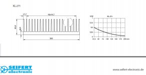
BTW, using the same KL271 on my AJ.
that thermal resistance looks a little optimistic.
you do not get half the thermal resistance with doble hight. you need 4 times the hight to half the thermal resistance. and at what temp are this numbers? 80c above ambient? that is a sink temp of 120-125c. and that you don't want
you do not get half the thermal resistance with doble hight. you need 4 times the hight to half the thermal resistance. and at what temp are this numbers? 80c above ambient? that is a sink temp of 120-125c. and that you don't want
i moved to A60 thread heat sinking is to offtopic here
http://www.diyaudio.com/forums/pass...ed-guide-aleph-60-builders-5.html#post3663368
http://www.diyaudio.com/forums/pass...ed-guide-aleph-60-builders-5.html#post3663368
ticktock. whats the hight of your sinks? and what is the sink temp on your aleph J?
150 height x 300 mm long, 85 mm deep. Still don't have IR thermo yet, but I can touch it.
From what I remember K/W is about 0.12 or so. This seems to to correlate with the above graph.
Last edited:
You might use one of these neat things, instead of clumsy legacy type coils:
Mini Electronic Choke
Electronic Choke
For low current apparatus like tubes and preamps though...
Mini Electronic Choke
Electronic Choke
For low current apparatus like tubes and preamps though...
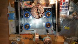
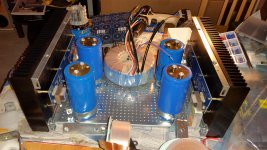
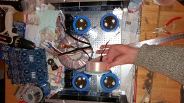
I am building a Firstwatt F6 with a CLC. There are so many things to consider, and so tight space. This is how far I have come in a few weeks. 70.0000uF - 2.7mH 0.45 ohm air coil 70.000uF, bypassed by 10uF film cap on each side. The amp is stereo, not mono, and I am basically replacing the reisistors in a diyaudio universal psu board with the coils. How am I supposed to mount them, with regards to power trafo, F6 audio transformer and each other ( the coils)?
Attachments
Last edited:
have you any choice?
I would try to squeeze Donut vertically , behind front panel ....... if height of case permit
then chokes (lil' Donuts) laying between caps
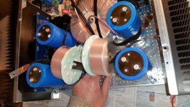
I can fit it but the Sedelbauer power trafo would pressed against the lid making a small bump in the lid. It is quite huge. Can the hamburger sized coils (not a donut fan) be placed vertically between the blue caps, facing each other with a 5 cm distance from each other? They would be 0.5cm away from the power trafo, which is a BIT CLOSE. Distance to audio trafo would be 9cm which is nice.
Imagine the right coil. I needed my other hand to take the picture.
I am thinking I want to keep them away from the audio trafos on the F6 boards. You can see them in the lower corner.
Attachments
Last edited:
- Status
- This old topic is closed. If you want to reopen this topic, contact a moderator using the "Report Post" button.
- Home
- Amplifiers
- Pass Labs
- PI-filter (or CLC vs CRC vs C)