Just wondering if these https://www.madisoundspeakerstore.com/steel-laminate-15-awg/steel-laminate-3.3-mh-15-awg-inductors/ would work. They are relatively cheap.
I used the 3.7 mH Madisound sledgehammer coils (0.2 ohms) in a dual mono CLC p.s. for a Aleph J. The main problem with coils is they take up some room and you should allow a little space between them and the power transformer, each other and certainly an input transformer if you have an F6. I had to put the power supply in a different enclosure with most of the last C in the amp enclosure. I did not have the time or money to experiment with different coils, but my p.s. was very effective and quiet. Someone on this forum did a test and found ideal cap distribution was near 50%/50% for a CLC. However, 30%/70% was also good for a CLC.
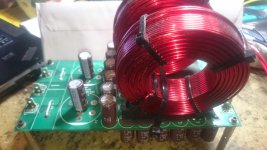
My 50/50 CLC for the op stage on my class A.
Discovered a saturation issue because of the high current when using the sledgehammer. Hence I went with a air coil only inductor. Still gets a little hot, but not
melting hot as when i first tried the 18 guage. Pictured is 14 AWG....
Discovered a saturation issue because of the high current when using the sledgehammer. Hence I went with a air coil only inductor. Still gets a little hot, but not
melting hot as when i first tried the 18 guage. Pictured is 14 AWG....
Attachments
Last edited:
Great, thanks. You answered almost everything that I have been pondering for weeks now. Do you think a 2.7mH 0.46 ohm is too small? I will use two 70 000uf caps on each side of my CLC, fours caps total in stereo. Maybe there is a way to shield them from each other? I heard computer hardrives has a metal that shield magnetism.
Last edited:
My 50/50 CLC for the op stage on my class A.
Discovered a saturation issue because of the high current when using the sledgehammer. Hence I went with a air coil only inductor. Still gets a little hot, but not
melting hot as when i first tried the 18 guage. Pictured is 14 AWG....
I'm curious. What value sledgehammer did you use and how did you determine it was saturating. Also what size (caps etc.) is your power supply?
Hello,
Soon i will take a pair of Lundahl LL2733 chokes to a friend in Vietnam that he will use in a Nelson Pass design.
I will use the same ones in a Mcintosh power amp in the beginning of next year.
When the French did start using chokes in transistor power amps. They also used values like 100 /200 mH. Of course these are no air coils.
Especially if you are located in Sweden you should try these!
Greetings, Eduard
CLC = 10 x 1000uF (low impedance) / 2.2mH / 10 x 1000uF (low impedance)
Just curious, how did you arrived at the value of the inductor? Thanks!
Regards,
Hello,
Soon i will take a pair of Lundahl LL2733 chokes to a friend in Vietnam that he will use in a Nelson Pass design.
Hi,
I found a nice guide to using the Lundhal chokes. Lundahl Plate chokes, Lundhal Anodendrossel
I don't know how much of it is true. He says all transformers will start to hum if you connect a cap directly after it. He recommend a resistor in a R-C-L-C.
Just curious, how did you arrived at the value of the inductor? Thanks!
Regards,
It was simmed on LTspice
Hi,
I found a nice guide to using the Lundhal chokes. Lundahl Plate chokes, Lundhal Anodendrossel
I don't know how much of it is true. He says all transformers will start to hum if you connect a cap directly after it. He recommend a resistor in a R-C-L-C.
Hello,
He only uses the resistor to adjust the output voltage.
Choke input is very nice but you will need a powert transformer with higher secundary voltages. Not so easy. BUT it is easy to change CRC into CLC
We will see what happens in Vietnam with the ll2733
Greetings, eduard
I'm looking at the issue of C R C vs C L C for a power supply for an F5,
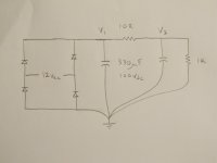
so I performed a small low current test using the attached schematic.
Both electrolytics were the same value 330uF @ 100 Vdc.
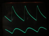
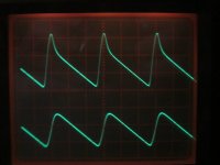
With the scope set to 100mV / div. you can see the first cap takes the brunt of the ripple.
If I understand things correctly, the power dissipated inside the cap is caused by the ripple x ESR , which is going to create heat.
Then the 10R was replaced by 180uH and it appears to be an under dampened system.
Recall, in an ideal system Zeta = 1/sqrt(2) .
The 180uH inductor was an air core, so I doubt a few milliAmps of current would have put it into saturation.
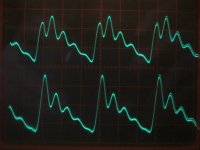
So I added 3R3 in series with the 180 uH inductor to reduce the Q of the inductor and the C L C filter behaved nicely.
But who knows if its over damped now ?
For an F5 power supply, keeping fo to a very low frequency would certainly help.
For example, if the filter is 3 x 12,000 uF ==> 2.5mH ==> 3 x 12,000uF
that would give a total C = 72 mF.
fo = 1 / ( 2 x pi x Sqrt ( L x C )) = 11.9 Hz
However, I still think making sure the C L C is properly damped would be good.
SPICE would be very helpful here so the filter could be looked at in frequency domain - unfortunately, I'm not set up for it.
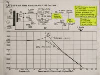
Actually, here is is a pretty good article concerning transfer functions and damping L C and C L C filters.
https://www.ti.com/lit/an/snva538/s...08690&ref_url=https%3A%2F%2Fwww.google.com%2F
So the question is if the Hammond 159 ZL inductor has a DCR = 0.044 Ohms,
how can I figure out if that is enough to correctly dampen the C L C ?
......... Test Circuit ................ C 10R C ................. C 180uH C ............... C 180uH + 3R3 C .............. Cook Book dampening
so I performed a small low current test using the attached schematic.
Both electrolytics were the same value 330uF @ 100 Vdc.
With the scope set to 100mV / div. you can see the first cap takes the brunt of the ripple.
If I understand things correctly, the power dissipated inside the cap is caused by the ripple x ESR , which is going to create heat.
Then the 10R was replaced by 180uH and it appears to be an under dampened system.
Recall, in an ideal system Zeta = 1/sqrt(2) .
The 180uH inductor was an air core, so I doubt a few milliAmps of current would have put it into saturation.
So I added 3R3 in series with the 180 uH inductor to reduce the Q of the inductor and the C L C filter behaved nicely.
But who knows if its over damped now ?
For an F5 power supply, keeping fo to a very low frequency would certainly help.
For example, if the filter is 3 x 12,000 uF ==> 2.5mH ==> 3 x 12,000uF
that would give a total C = 72 mF.
fo = 1 / ( 2 x pi x Sqrt ( L x C )) = 11.9 Hz
However, I still think making sure the C L C is properly damped would be good.
SPICE would be very helpful here so the filter could be looked at in frequency domain - unfortunately, I'm not set up for it.
Actually, here is is a pretty good article concerning transfer functions and damping L C and C L C filters.
https://www.ti.com/lit/an/snva538/s...08690&ref_url=https%3A%2F%2Fwww.google.com%2F
So the question is if the Hammond 159 ZL inductor has a DCR = 0.044 Ohms,
how can I figure out if that is enough to correctly dampen the C L C ?
......... Test Circuit ................ C 10R C ................. C 180uH C ............... C 180uH + 3R3 C .............. Cook Book dampening
Attachments
Last edited:
In a CLC power supply filter , I think the L needs to be dampened.
Certainly, it would be good to have a look at this in the frequency domain.
Page 8 of the ti application note says the dampening can be done by connecting an R + L in parallel across the L.
Fortunately, Ozorfis looked at this exact issue with a hammond 159ZL ( 2.5mH and r = 0R044 )
and recommended connecting a 0R2 20 watt resistor in series with this hammond choke.
CLC vs. CRC
I have to get set up for SPICE - the last I used it was on a PDP-11.
.
- Status
- This old topic is closed. If you want to reopen this topic, contact a moderator using the "Report Post" button.
- Home
- Amplifiers
- Pass Labs
- PI-filter (or CLC vs CRC vs C)