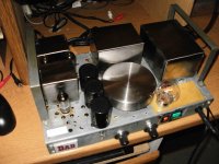
Inside is a modified Sony Playstation 1,first version.Dac is direct coupled via a RF filter network to a 12b4 gain stage which provides the small amount of gain to get this to normal CDP output levels.12B4 power supply is external.PS1 power supply has been replaced with a linear PS.It is a bit tempermental reading some CDs even after making adjustments,so some more work is required here.This is an excellent sounding CD player.Very analog and natural,as close to vinyl as any CDP I have heard.pebmrb:
Great job!
Can you provide circuitry details?
Jim
The Eyepod:Very nice work pebmrb! I would love to see close ups of the other two pieces of equipment on that rack.
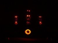
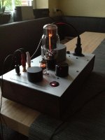
An EL84 amp
Attachments

Last edited:
Also on the rack is a matching phono stage,I don't currently have pics of that.The rack itself is an interesting piece.It's a old cast iron sewing machine stand from the late 1800s which someone had put in the trash.A couple shelves added creates a nice,steampunk stereo stand.
I agree with diodes. The 81 further is not an audio valve probably better to control it. About 82 Different animal. To Popilin friend is a nice tube. SN7 is better- Did you tried 5751? ECC808?
Best Regards for you.
Thanks for the comments guys. I stuck with the original Mullard valve set ie ecc83 and two el84. As for the HT diodes, I went back to the silicon bridge and just used half of the bridge instead of two 1N4007's and the sound is better.
Latest pic with full covers. The amp sounds nice for guitar sounds and for my rock and roll moods.
Attachments
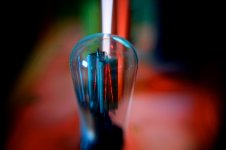
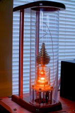
New (more artistic) pics of my 4-65a amps
Some were taken in HDR and some with a Lensbaby and speed adapter.
Original post back from last year when the amp was first completed.
http://www.diyaudio.com/forums/tubes-valves/71300-photo-gallery-463.html#post3328592
One change is that it's gone from a d3a as input tube to a e280f. This input tube has about 3.2v bias from two AA batteries. It avoids problems I had with running the d3a into A2, and I think sound a bit better as well.
-MW
Attachments
Some were taken in HDR and some with a Lensbaby and speed adapter.
Original post back from last year when the amp was first completed.
http://www.diyaudio.com/forums/tubes-valves/71300-photo-gallery-463.html#post3328592
One change is that it's gone from a d3a as input tube to a e280f. This input tube has about 3.2v bias from two AA batteries. It avoids problems I had with running the d3a into A2, and I think sound a bit better as well.
-MW
Is Frankenstein, the monster is behind the 4-65A-
I will imitate your style sir is the better I saw in this topic.
It took me over two years in planning and construction, but they're finally completed! It was as much an exercise in aesthetics, as it was for sound quality. That is to say, they sound at least as good as they look!
-MW
This is what seperate men from boys!
Great job! Very Inspirational!
...Since the 6SN7 driver also operates as a differential amplifier, we may as well employ this same technique there as well, to preserve good balanace going into the KT88s.
This is how it should be in theory, if the output tubes and OPT would be ideal, which they are not.
I have observed that the minimum THD is achieved when not only the DC-balance, but also the AC-balance can be adjusted.
Therefore the perfect AC-balance at the output of LTP should not be a design goal, but of course the minimum overall distortion should be.
I agree, of course.
In this design I've taken the approach of trying to optimize each individual stage, rather than have one stage make up for the imperfections of another. For example, I believe the output stage should be as close to balanced as possible, rather than have the driver or splitter be slightly unbalanced to make up for the deficiencies of the output stage.
Overall distortion of this design is about 0.05% when the signal is about 5 dB below clipping, so I'm pleased with the result. (This is with feedback)
At present the output tubes (KT88s here) still need to be hand-selected. I'm looking at ways to improve the balance of the output stage too, but since it's running in class AB, the solution is not so simple as for a LTP.
To independently adjust the AC and DC balance of the splitter I describe, one could provide an "extra" pair of resistors from the plates to the base of the NPN, with capacitive coupling from these two resistors to each plate. Then a portion of each pair of resistors (AC pair and DC pair) could be a potentiometer, if desired.
I agree with your assessment, of course- I've emphasized balance here, which minimizes even-order distortion- but there's still the nonlinearities in the transfer functions of the devices used in the splitter, driver and output(!) to be concerned with, in order to minimize odd-order distortion. All I've been able to do here is to choose a Q point in the middle of the most linear region of the transfer function.
Last edited:
I've read in several places (including Morgan Jones) that cascading differential pairs helps put them in better balance. Also, putting constant current sinks in the tails of the differential stages greatly improves balance. So while an adjustment would certainly help you dial in near-perfect balance, the tubes would drift over time, necessitating periodic balance adjustments to maintain that near-perfection.
This would need to be measured, but shouldn't two cascaded differential pairs, each with ccs in their tails, balance pretty well by themselves? (Assuming decently matched-pair triodes in the differential pairs, of course.)
--
This would need to be measured, but shouldn't two cascaded differential pairs, each with ccs in their tails, balance pretty well by themselves? (Assuming decently matched-pair triodes in the differential pairs, of course.)
--
They will balance perfectly, or near enough to "perfectly" not to matter- I've posted some experimental results demonstrating this under even ridiculous conditions. This scheme is almost identical to the CCDA amps designed and sold by Ike Eisenson in the late '70s (though he used LED references for the CCS), and of course, a direct coupled version with some added features is used in the Crystal Palace. Cascoded CCS are a nice touch, but I'm unconvinced that they help overall performance. But if you're a perfectionist, they only add a dollar or two to the BOM.
Yes, one could deliberately unbalance the phase splitter to partially compensate for output stage imbalance, but this will not be stable over time. IMO, best to get the output stage well-balanced from the get-go, then use a high quality phase splitter like this one.
Yes, one could deliberately unbalance the phase splitter to partially compensate for output stage imbalance, but this will not be stable over time. IMO, best to get the output stage well-balanced from the get-go, then use a high quality phase splitter like this one.
Yes, the LTP with a CCS in the tail does indeed balance very well by itself. I'm pleased without any AC or DC adjustments, and the stage I've described is dependent on the match of the two 820k resistors, so tube aging should not be a factor.
I mention the bit about providing separate AC and DC balance adjustments for artosalo, who seemed interested in varying the balance to tune for minimum overall distortion.
I've tried this (tuning) and after a few weeks, realized I was chasing my tail. Better to linearize each stage than to complicate the design with a lot of adjustments that are bound to change with time. It's bad enough to have DC balance and bias pots in the output stage, without compounding the complication by having separate AC and DC balance adjustments in each stage. Tuning adjustments are for IF strips, not the audio stage, I figure.
100% agreed.
Using the CCS tail means that the stage balance is entirely dependent on the plate resistors and has no dependence on tube parameters, which is a good thing.
Not to hijack the thread, but this begs a question about amps that use a single diff-pair as a phase splitter/driver stage.
If you use a medium mu tube like 5687 or 6N6P as the lone LTP, and put a ccs in its tail, with a single common-cathode stage in front of it, how capable a driver is this compared to the two-cascaded differential stages driver? Distortion will be that much higher?
This scheme is almost identical to the CCDA amps designed and sold by Ike Eisenson in the late '70s (though he used LED references for the CCS), and of course, a direct coupled version with some added features is used in the Crystal Palace.
...And JC Morrison's "Tubeosaurus" and a similar amp by Arthur Loesch published in Sound Practices in the early 1990's. I recently built something like this in a Dyna Stereo 70 chassis, on a dare. A friend built this type of amp with all DC-coupled stages and 300B outputs. Every one of this type of amp that I've heard has sounded really good, at least to me. I don't know why more people don't use this topology.
--
Distortion will be that much higher?
Some (mostly 2nd harmonic) but not a lot. If you get the gain of the first stage high, feedback will drop that distortion considerably.
- Home
- Amplifiers
- Tubes / Valves
- Photo Gallery