to make frankenstein movies atmosphere it would be needed to have buzzing jacobs ladder, dim lights..Is Frankenstein, the monster is behind the 4-65A-
I will imitate your style sir is the better I saw in this topic.
those plate plugs just awesom
...I mention the bit about providing separate AC and DC balance adjustments for artosalo, who seemed interested in varying the balance to tune for minimum overall distortion....
When I mentioned the DC-balance adjustment, I referred to bias balance adjustment of the output tubes, not of LTP's.
To me it is obvious that if this adjustment is needed, as it usually is, then AC-balance adjustment somewhere in the circuit is needed too.
If one can have perfectly matched output tubes and therefore could omit both adjustments, does he still have such situation after a year of listening ?
I am not sure about this.
<snip>
If one can have perfectly matched output tubes and therefore could omit both adjustments, does he still have such situation after a year of listening ?
I am not sure about this.
I've only encountered a very few 300B (JJ and NOS WE) and genuine MOV KT88 that stayed well matched over time. I think it is fairly safe to assume that there will be parametric shifts over time in most power tubes. Tubes that were burned in for 24 hours or more prior to matching seem better in this regard, but even here I have seen significant drift of parameters.
Companies like Tektronix and HP extensively burned in small signal tubes prior to matching and grading for applications where drift and section to section balance over time were critical.
Any info/schematic? Listening report?My everyday amp is GM-70 SET.
If one can have perfectly matched output tubes and therefore could omit both adjustments, does he still have such situation after a year of listening ?
I am not sure about this.
In the past many output transformers were suitably dimensioned to accept 10-20% out of balance current in the primary halves and the AB global nfb doing the correction job. However, my old Linear 807 amp of 1959, the o/p tube mismatch was found way above 30%, and the thd was still reasonably low.
None of these tube amps in the past had any bias adjustments in their life time. One just bought "recommended replacement tubes" for that model. Of course nowadays; a recent made JJ 84 won't have the same bias point as a Mullard would and most of us know this.
richy
I designed a simple monitoring PC that displays bias current and will show a 5mA mismatch. The thought is to use it to monitor the health of the output tubes and use it for adjusting the bias to minimize core saturation for best bass response. It can be turned off when not wanted.
Attachments
I got suspicious when I started to use the Tungsol New Ed 6550, as previously noted sometime ago the whole B clear getter series has a far longer warm up time than other tubes in it's class. Hence the bias tended to wander. I'd even suspected 7V heaters instead of 6.3 were being used.
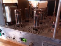
I can recommend any digital monitor plus a small reggy for the 5V; Farnell and others do; using 1% tolerance resistors and careful series resistor selection for those on the HV side plus a 12 way switch to complete other voltage measurements too. see pic of display on 500W fixed bias leviathan amp using 8x KT90's. Power amps of this class do need some early warning, even the ones in the past had some indicator.
Now it is possible to get a proper assessment of when tubes really start to drift on the condition that the Bmax and neg bias is steady..
richy
Attachments
Yes- output tubes will drift and change over time, so the balance is most likely not the same as it was the day the amp was built. Even then, when purchasing a "matched pair" the matching is usually done on a DC-only basis, i.e. how much plate current flows for a given set of bias conditions. I don't think tubes are routinely matched based on both DC and transconductance... I wish they were!
If anyone knows differently, I'd be pleased to hear of my error!
Trimming the output stage for both AC and DC balance is not a bad idea. Better still to devise a circuit to to this automatically (like the hybrid splitter described earlier) and a means to alert the owner/listener when the parameter drift has exceeded a certain limits.
Artosalo - I didn't realize you were referring to the output stage. I incorrectly assumed you meant the splitter. Apologies.
It's perhaps worth exploring a means to self-correct output tube AC and DC drift. Has anyone ever encountered a circuit topology or a design approach to do this? It may be worthwhile to assume this as a development project if prior art does not exist in this area.
Bench Amp
OK... True Confessions: I spend a good deal of time listening to an amp with somewhat less performance than the penultimate. I suppose in terms of HOURS, I spend more time per year listening to this little amp in my basement than in listening to anything else. So I guess this also qualifies as my "every day tube amp".
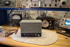
After designing and building a more reasonably-sized amp (KT-88 outputs) I decided to build one using 6AQ5 tubes. Despite its miniature size the 6AQ5 is a true beam power tube and does not use a helically-wound suppressor grid like the 6BQ5. With its 7-pin miniature base, it's the smallest beam power tube I know of. Always been curious what a pair of these will do. I've also needed a small (5-10W) high-quality design in my hip pocket, ready to use on the workbench, or for the output of a nice AM/FM receiver (some day!).
I built this one as a general-purpose amp for the workbench. RCA inputs front & rear, 3/4" banana input front, 3/4" banana outputs front & rear, terminal block output rear.
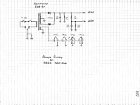
The power transformer could be a little bigger; it's the closest I could find to my needs from Hammond. I wanted to keep this SIMPLE and small so it's cathode bias, not fixed-bias, and since the power level is small, this works out well.
Surprisingly, I found that even at this low power level, I still needed both voltage amp stages to provide enough gain, given a moderate level of overall feedback. In this case, I still use a 12AX7 for the splitter, but can get away with the lower-voltage 12AU7 driver instead of the 6SN7 used in my KT-88 design. Other than that, there's a very strong family resemblance in the schematic.
Errata: The power supply references all heaters as for 6AQ5. The last two (with center taps) are of course for the 12AX7 and 12AU7.
When it isn't being used to monitor or measure some portion of a circuit under development, I usually feed it from an H.H. Scott 350B tuner (in mono). A nice little amp!
5W
.05% THD
20-20k +- 1DB
noise < -80dBV
22dB feedback
0dBV input will drive it to clipping.
Sounds great. Nothing annoying or obviously "wrong"-sounding. Very transparent, it seems to add no sound or character of its own. At only five watts, it certainly won't make your ears bleed, but it fills the room to a volume as loud or louder than I really need most of the time- and it does so cleanly. Would make a great output stage for a table radio, etc.
OK... True Confessions: I spend a good deal of time listening to an amp with somewhat less performance than the penultimate. I suppose in terms of HOURS, I spend more time per year listening to this little amp in my basement than in listening to anything else. So I guess this also qualifies as my "every day tube amp".
After designing and building a more reasonably-sized amp (KT-88 outputs) I decided to build one using 6AQ5 tubes. Despite its miniature size the 6AQ5 is a true beam power tube and does not use a helically-wound suppressor grid like the 6BQ5. With its 7-pin miniature base, it's the smallest beam power tube I know of. Always been curious what a pair of these will do. I've also needed a small (5-10W) high-quality design in my hip pocket, ready to use on the workbench, or for the output of a nice AM/FM receiver (some day!).
I built this one as a general-purpose amp for the workbench. RCA inputs front & rear, 3/4" banana input front, 3/4" banana outputs front & rear, terminal block output rear.
The power transformer could be a little bigger; it's the closest I could find to my needs from Hammond. I wanted to keep this SIMPLE and small so it's cathode bias, not fixed-bias, and since the power level is small, this works out well.
Surprisingly, I found that even at this low power level, I still needed both voltage amp stages to provide enough gain, given a moderate level of overall feedback. In this case, I still use a 12AX7 for the splitter, but can get away with the lower-voltage 12AU7 driver instead of the 6SN7 used in my KT-88 design. Other than that, there's a very strong family resemblance in the schematic.
Errata: The power supply references all heaters as for 6AQ5. The last two (with center taps) are of course for the 12AX7 and 12AU7.
When it isn't being used to monitor or measure some portion of a circuit under development, I usually feed it from an H.H. Scott 350B tuner (in mono). A nice little amp!
5W
.05% THD
20-20k +- 1DB
noise < -80dBV
22dB feedback
0dBV input will drive it to clipping.
Sounds great. Nothing annoying or obviously "wrong"-sounding. Very transparent, it seems to add no sound or character of its own. At only five watts, it certainly won't make your ears bleed, but it fills the room to a volume as loud or louder than I really need most of the time- and it does so cleanly. Would make a great output stage for a table radio, etc.
Attachments
Last edited:
A VERY nice looking amp you built yourself. It has a very clean and old time look to it with the cover, knob, colours, and the jewelled pilot light on the front. Clean on the outside and clean on the inside with the wiring.
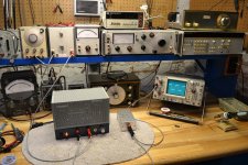
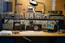
And to make things even more enviable... that work bench with variac, tone generator, voltmeter, and machine that goes "ping" (okay I am not sure what else is up there, but maybe one goes ping) is a little bit of awesomeness.
Curious though, what do you output the sound to?
And to make things even more enviable... that work bench with variac, tone generator, voltmeter, and machine that goes "ping" (okay I am not sure what else is up there, but maybe one goes ping) is a little bit of awesomeness.
Curious though, what do you output the sound to?
The workbench has almost enough gadgetry to keep me amused... There's always "just one more thing" - but it does serve my needs pretty well.
I don't dump the output into MUCH, that's for sure. A JBL one cubic foot 2-way bookshelf. It's sort of OK for listening to local FM or a CD while I'm working at the bench. By no means Hi-Fi. Mid-Fi at best.
Hmmm.... Maybe a speaker project...?
I don't dump the output into MUCH, that's for sure. A JBL one cubic foot 2-way bookshelf. It's sort of OK for listening to local FM or a CD while I'm working at the bench. By no means Hi-Fi. Mid-Fi at best.
Hmmm.... Maybe a speaker project...?
According to my experience 22 dB GNFB is quite high with Hammond transformers.
Could you show what 5...10 kHz square wave looks like at some 2...3 W level ?
There is common cathode resistor for output tubes. This emphasizes possible DC-unbalance. Separate cathode resistors are usually better choice.
The THD reading is presumably at 1 kHz and at 5W.
How about at 20 Hz and at 10 kHz ?
I'm comfortable with somewhere around 15-25 dB feedback. There's not much to be gained beyond that. 20dB is, after all, 10:1, so damping factor should be around 10 and THD is lowered by a factor of 10 -beyond that, I'd be asking NFB to cure a fundamental design problem rather than solving the problem itself.
As long as the transformer has minimal phase shift over the audio passband, stability criteria are usually easily met- this case being no exception.
I will say the following about feedback in this design:
1. 22 dB is plenty. It's about as much as I feel comfortable using in this design.
2. The output transformer matches a 10,000 ohm primary to an 8 ohm load - quite a turns ratio, and quite a chance for stray capacitances an leakage inductance to become a problem. This case seems fine, but this turns ratio is about as high as I'd want to use routinely.
If I eliminate the 12AU7, I would have just barely enough gain to drive the amp to clipping with 1 VRMS input. If I include the driver, I'd have 22 dB "excess" gain that I can use for NFB. So I included the driver.
Hammond transformers seem about as good as any- I've never encountered any particular issues with them - wonder if you have? -Certainly toroids give better performance, but for a relatively inexpensive off-the-shelf design using E-I laminations, Hammond seems pretty good to me. -Anyone else care to comment? I'm always eager to learn of an alternate source with equal or better performance at about the same price.
I used a single cathode resistor to improve the dynamic balance; it operates a bit (a LITTLE bit) like a CCS and helps slightly. I could have used separate cathode resistors, each resistor will linearize its associated tube, but the value is then double, and the gain decreases somewhat. Although two resistors gives the ability to hand-match the DC parameters of the output tubes, the AC parameters are only slightly affected by this matching - and as I've said before, hand-tuned adjustments are for IF strips, not the audio stage. A single cathode resistor is preferred.
I bought the 6AQ5s as a matched pair, and whatever matching was done by the supplier seems to give good performance; I'm pleased with the performance measurements.
I had the amp itself on the bench a few minutes ago to take pictures of the square wave response you wanted to see.... and I forgot to make THD measurements at the frequency extremes! -But when I built the amp I did measure "power bandwidth" - With the amp driven near clipping, I noted the high- and low- frequencies at which the THD began to rise sharply from the midband value.
The power bandwidth of this amp is 22 Hz - 32 kHz.
The small-signal response is designed to be 1 dB down at 20 Hz and at 20 kHz, which means that the 3db points are 10 Hz and 40kHz.
Here are a few more pictures:
1. Square wave test setup
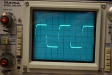
2. 5 kHz square wave near clipping
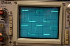
3. Upper trace: 5kHz sq wave at about 2 W out
Lower trace: sq. wave through a 40 kHz RC filter to duplicate the small-signal response of the amp - for comparison.
4. A shot of the whole wretched workbench. Relics from the mid-1970s, but it makes me happy. Everything works well and is reliable. Someone was asking about the speaker I drive with this amp. This is it, there in the upper-left. Like I say, "True Confessions". 'Nuff said.
As long as the transformer has minimal phase shift over the audio passband, stability criteria are usually easily met- this case being no exception.
I will say the following about feedback in this design:
1. 22 dB is plenty. It's about as much as I feel comfortable using in this design.
2. The output transformer matches a 10,000 ohm primary to an 8 ohm load - quite a turns ratio, and quite a chance for stray capacitances an leakage inductance to become a problem. This case seems fine, but this turns ratio is about as high as I'd want to use routinely.
If I eliminate the 12AU7, I would have just barely enough gain to drive the amp to clipping with 1 VRMS input. If I include the driver, I'd have 22 dB "excess" gain that I can use for NFB. So I included the driver.
Hammond transformers seem about as good as any- I've never encountered any particular issues with them - wonder if you have? -Certainly toroids give better performance, but for a relatively inexpensive off-the-shelf design using E-I laminations, Hammond seems pretty good to me. -Anyone else care to comment? I'm always eager to learn of an alternate source with equal or better performance at about the same price.
I used a single cathode resistor to improve the dynamic balance; it operates a bit (a LITTLE bit) like a CCS and helps slightly. I could have used separate cathode resistors, each resistor will linearize its associated tube, but the value is then double, and the gain decreases somewhat. Although two resistors gives the ability to hand-match the DC parameters of the output tubes, the AC parameters are only slightly affected by this matching - and as I've said before, hand-tuned adjustments are for IF strips, not the audio stage. A single cathode resistor is preferred.
I bought the 6AQ5s as a matched pair, and whatever matching was done by the supplier seems to give good performance; I'm pleased with the performance measurements.
I had the amp itself on the bench a few minutes ago to take pictures of the square wave response you wanted to see.... and I forgot to make THD measurements at the frequency extremes! -But when I built the amp I did measure "power bandwidth" - With the amp driven near clipping, I noted the high- and low- frequencies at which the THD began to rise sharply from the midband value.
The power bandwidth of this amp is 22 Hz - 32 kHz.
The small-signal response is designed to be 1 dB down at 20 Hz and at 20 kHz, which means that the 3db points are 10 Hz and 40kHz.
Here are a few more pictures:
1. Square wave test setup
2. 5 kHz square wave near clipping
3. Upper trace: 5kHz sq wave at about 2 W out
Lower trace: sq. wave through a 40 kHz RC filter to duplicate the small-signal response of the amp - for comparison.
4. A shot of the whole wretched workbench. Relics from the mid-1970s, but it makes me happy. Everything works well and is reliable. Someone was asking about the speaker I drive with this amp. This is it, there in the upper-left. Like I say, "True Confessions". 'Nuff said.
Attachments
If that is your workbench with your everyday amp, that would lead me to believe that you work at that bench everyday. You sir, have given me a goal to reach (mind you, it is in there with a few other goals and behind some priorities).
I showed my wife your workbench. She said, "...that's nice. You should send him your Jacob's Ladder." and walked away (she doesn't like my homemade Jacob's Ladder because of voltage, arcing, or something silly like that... I like it though.).
Well, the speaker is probably well equipped enough to handle the power of the amp (which was partially why I was curious) and are there any other amps that you have built in the past?
There are different design philosophies. I try to avoid GNFB above some 15...16 dB.
At the same time I tend to have the frequency response as high as possible and THD minimized by optimizing every stage separately or using distortion cancelling when possible.
I have had stability problems with Hammond 1608 even below 20 dB GNFB, but the reason then was maybe the attempt to have maximum high frequency response.
Your 5 kHz square wave response looks good, no sign of ringing, but a bit limited transient response (rounded square).
Your workbench looks liken mine, execep mine is allways messier...
I even have similar HP 333A and Radiometer SMG1 Stereo generator.
By the way; do you have a service manual for the latter ?
I built one using KT-88 output tubes, about 65WPC. See my entry earlier in this thread, posting No. 108 -and the discussion on splitters that follows.
Jacob's ladders are FUN! -Especially larger ones, given that you have room for it! So are Wimshurst generators - just frightful! Anything that produces lightning has GOT to be fun, right? I think a tesla coil would be great fun to drag out on Halloween if you can keep the general public at a safe distance.
Jacob's ladders are FUN! -Especially larger ones, given that you have room for it! So are Wimshurst generators - just frightful! Anything that produces lightning has GOT to be fun, right? I think a tesla coil would be great fun to drag out on Halloween if you can keep the general public at a safe distance.
Artosalo-
It seems each of us has a very reasonable yet markedly different design approach. That's what makes this forum so interesting!
The rounded square is of course due to the 40 kHz bandwidth, as you saw by comparing the amp's output with a 40 kHz RC filter. To speed up the rise time would require a greater bandwidth, and since it's already only 1 dB down at 20 kHz, I'm happy. The response should be limited at SOME point, so a square wave will always have a rounded (RC-characteristic) rise and fall. At least it doesn't seem like it's about to oscillate- no excessive ringing, etc.
The HP 334 suits my needs well. I'd like a better oscillator- this one measures 0.065% THD, so when I measure 0.07% out of the amp, I can only guess at what the real number might be. And alas, a low-distortion oscillator costs real money.
The decade attenuator is a must-have. It's so convenient to vary the level in precise 1dB or 10dB steps.
I found the Radiometer SMG1 on eBay -What a find! -I replaced ALL the electrolytics in it - every single one. 75% of them were leaky enough to seriously degrade performance. Expensive, time-consuming, but worth every dollar and every minute. A decent stereo generator, and very handy to have on the bench!
I do not have a service manual for it, unfortunately. I'd love to have one.
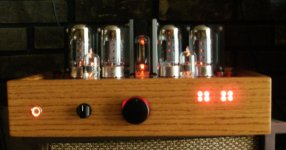
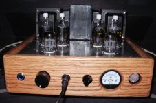
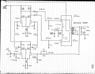
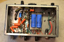
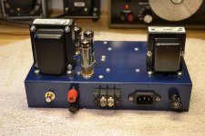
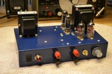
Maybe I also show something I have done. This is one of my today's amplifier.
It is based on Tesla QQE03/12 double tetrodes as a pentode connected output tubes and soviet 6f12p triode-pentodes as a voltage amplifier and cathodyne phase splitter.
Output power is 10 W with less than 1 % THD while at 1 W THD is less than 0,2 %. Frequency response (1 dB) is 20 Hz...70 kHz. Output impedanse 1 ohms and GNFB used only 14 dB.
I have built few pieces of these.
I have used the features I mentioned earlier: both DC and AC-balance adjustments.
The size is relatively small, just 215 mm X 190 mm X 145 mm.
An externally hosted image should be here but it was not working when we last tested it.
An externally hosted image should be here but it was not working when we last tested it.
An externally hosted image should be here but it was not working when we last tested it.
An externally hosted image should be here but it was not working when we last tested it.
An externally hosted image should be here but it was not working when we last tested it.
An externally hosted image should be here but it was not working when we last tested it.
Last edited:
- Home
- Amplifiers
- Tubes / Valves
- Photo Gallery