georgehifi said:People like Berhard are using 300ohms odd for passive I/V resistor loading of the dacs, if the zap is 25ohm then now with the 100ohm that I put in in series it sees 125ohm, still way under (better) than what the passive I/V resistor brigade are saying, and it sounds magnificent.
Berhard is using 8 dacs per phase to get higher output current, therefore he is able to use relatively low value resistor for passive conversion to get distortion down...But his dac will newer ever see near zero impedance, virtual ground input of an active stage like yours...if you get ride of 100R.

aparatusonitus said:
Berhard is using 8 dacs per phase to get higher output current, therefore he is able to use relatively low value resistor for passive conversion to get distortion down...But his dac will newer ever see near zero impedance, virtual ground input of an active stage like yours...if you get ride of 100R.
8 DACs
= 8 x 250 ohm
= 31 ohm
= close to virtual ground
Voltage swing on each phase
= 250 mV
= 500 mV phase to phase
= 1 V after 1:2 transformer
aparatusonitus said:
I don't think you should put any resistor in series with the dac output...the dac will see a 100R+Re impedance, instead (theoretically) zero impedance from active I/V. What I would do is to half the values for R19/20 'cos that is the point where actual current to voltage conversion is taking place. Adjust values of C2/3 appropriately, as well as values of R17/18 (just a bit higher, start with 210R and up) until you get the lowest output DC offset without servo opamp installed.
aparatusonitus if I do this it will reduce the gain of the Zap?
If so this is not what I need, I need to increase the head room of the zap, as it just soft clips at 0dbf without the 100ohms at the input.
Cheers George
Attachments
georgehifi said:aparatusonitus if I do this it will reduce the gain of the Zap?
It will reduce the gain by half.
aparatusonitus said:
It will reduce the gain by half.
This is what I'm getting at, I do not need to reduce the gain of the Zap, I need to give it more headroom.
This is why I reduced the output from the dacs with the 100ohm in series, as this lowers the output of the dacs so it does not reach the zaps head room.
At 0dbf without the 100ohms the zap just soft clips, with the 100ohms it does not, I need to give the zap more headroom if I am to omit the 100ohm series resitor.
Cheers george
aparatusonitus said:Then rise the supply voltage to +/-15VDC...and lose the 100R
Since its the current that is at issue here. Would it also work to increase the power supply storage instead of ramping up the supply voltage?
I always thought the power supply for the Zap looked a little wimpy to me.
Were I to get it, it would be the first thing switched out.
The power supply that comes original for the output of george's dac is much larger and with much greater current capabilities.
champ04 said:Would it also work to increase the power supply storage instead of ramping up the supply voltage?
I don't think so...but you can easily put another fat filter cap in parallel with the original ones and see.
George,
Earlier in the thread you were working out a low pass filter using a capacitor. (due to oversampling, I assume.)
Did you consider using the inductors that are on your sledgehammer output?
Presumably, they would already be configured for a reasonable value in the system.
Wadia has been using them in series with the signal even before they created the sledgehammer buffer. You can find the same ones on earlier, passive output boards.
Maybe?
champ04 said:George,
Earlier in the thread you were working out a low pass filter using a capacitor. (due to oversampling, I assume.)
Did you consider using the inductors that are on your sledgehammer output?
Presumably, they would already be configured for a reasonable value in the system.
Wadia has been using them in series with the signal even before they created the sledgehammer buffer. You can find the same ones on earlier, passive output boards.
Maybe?
Found I didn't have to, as the H/F noise is minimal (10mv) at the Zaps outputput, as it has a L/P filter 4K02 and 470pf (-3db at 85khz) at the drivers, and I think a bit more filtering nearer the front end.
Cheers George
So here is a completely different direction I'm curious about......
I've been using my X64.4 to directly drive a set of earphones for months now. The earphones are the Etymotic ER-4. Their impedance is basically whatever size resistor is in series with the phones. In order to achieve an average output of 86dB across various recordings I replace their normal resistor with a 750R and run them directly from the Sledgehammer output buffer which is 2.5V, 400mA.
At 100 nominal impedance they are: 108 dB SPL for a 0.79 V input; 90 dB @ 0.1 V; 100 dB @ 1mW
At 27 nom. imp. they are: 108 dB SPL for a 0.2 V input; 102 dB @ 0.1 V; 106 dB @ 1mW
If I wanted to shoot for an average output of around 86dB......
What sort of combination of resistors am I looking at using in order to come directly off of the 4 parallel dacs? (btw, did we ever figure out what the actual output of those four PCM56 parallel is?)
Do I want to use just series, just parallel, or combination?
I'm thinking I need at least a parallel in order to get some l/V....... But how much.........
Revisiting this thread's ideas...........
I've pretty much gone sour on trying to add the Zapfilter into my Wadia 64.4 dac. Just doesnt seem neccesary.
In the end, the only thing I really wanted to do was get around the negative feedback of the opamps used for I/V.
So, going back to the 4 parallel PCM56K dacs used per channel that I'm starting with......
What should I be looking at as the best way to go passive?
I've already got a buffer circuit that I can follow it with if need be.
I'm also intrigued by the idea of using a transformer based circuit.
Anyone want to throw their two cents in? All ideas welcome.
I would leave the unit like it is, opamp i/v are not bad if done right. The icing on the cake would be to put a tube buffer / amplifier after the i/v. Personaly I dislike the sound of pcm56K as much as I like tda1541.
Now why on earth would I want to leave it like it is? Especially here at "DIY" audio!
Actually, one of my goals is to see what its like to eliminated negative feedback entirely from my system. Just for kicks. And the I/V of the DAC was the only remaining place.
FWIW, I spent some time fiddling with a transformer. It took some time and effort to get the loading just right. I can see why some people wouldnt want to bother. There is a lot of trial and error to it. But I am SO glad I did.
The difference between it and the opamps is not subtle. Now that I got the settings right there isnt any way I'm going back.
I finished the passive output for pcm56 and the result:
- Loss of deep bass,
- Frequency 1 kHz - 8kHz get a huge gain
- Imaging and detail is loss
- Total absence of realism in the sound
It's a disaster and I don't recommend it to anyone.
Check:
1) you have not disconnected the pins 9, 10, 11 from each other and from external circuitry.
Otherwise there are two loops!
2) I have once also seen external oscilation from the active I/V that was left dangling in the air so to say: so make a proper ground for the input of the existing opamp or take out the current supply!
cheers in the dark side of gnome land.
Thanks for help , the problem was impedance only, anyways I didn't liked the sound at all pcm56k. I could have build a proper tube stage , thanks for the help anyways, if you want it its a dbx cd player , the wires are already there for connecting to a new passive amplification, the output sockets need to be changed because I melted plastic inside lol. i also have a sony rail laser for advanced builders who could use it as a transport, its old stuff lol i could send the pcb cut in half too.
18 ohm + 100 nF ? where did you see that ?
That is more or less the same as if you shunt the Iout directly with 100nF to ground
Can not work.
Analog filter for a single PCM56 per channel, 200 ohm I/V:
Or for a 750 ohm I/V:
put 10nF ll to R_I/V.
No series resistor.
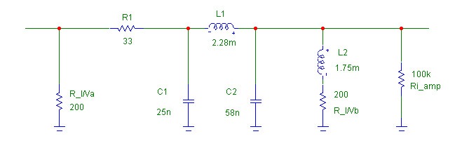
Bernard, starting from your schema and looking at what I have available, I changed it around a bit. I have 1 mH and 2 mH chokes.
Subsequently I loaded the schema I created in Broskies' tool and this showed me I had a nice approximation as well. Not as well thought out as yours of course.
Here is my schema:
R_I/Va 422 ohm
R_I/Vb 220 ohm
R1 33 ohm dale
C1 22 nF
C2 47 nF
L1 2 mH
L2 1 mH
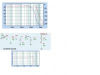
In the simulation it gives a slight rise at 20 kHz of 2 db and then an abrupt fall of > 18 db/octave.
As output I use an SRPP from the ECC88 family, running on a modest 80 volt, with a bandwidth of over 5-300 kHz. This amplifies 12x.
The sound: rich in harmonics, the slightest moan or sighting of a player and dubbed sounds can be heard clearly.
It is a musicality I like. It is a promising venue, for sure. Next I'll experiment with the clock.
As regards the Sony player I am tweaking, the CDP-590:
- I saw that the voltage regulator (+5v) got very hot; The result is that the capacitors get hot too (proximity); these are likely to dry out when they are on for an extended period of time! So I made a big heat sink. This improved the stability of the player too!
- The player skips a track with even slight disturbances, like tapping on the player.
- I disconnected the original output device and took out the power lines +/- 5V.
- I changed the capacitors to solid tantal 68 muF
Attachments
- Status
- This old topic is closed. If you want to reopen this topic, contact a moderator using the "Report Post" button.
- Home
- Source & Line
- Digital Line Level
- PCM56K iv resistor value?