Do you have the PCM56 inside the CDP-590 with digital filter ?
That schematic is for nonos only.
Yep, apologize of course. It retained 8x oversampling.
[I do have various TDA 1543 and TDA1541/A/S1 in NOS so I know how it should look like but strapping a SAA7220 is a piece of cake.]
So how should I NOS the digital filter CXD2554?
Netlist showed the schema (see
http://www.diyaudio.com/forums/digital-source/11867-cxd2552q-dac-datasheet.html#post137524) and that confuses me a lot

While out goes L/RDATA, in goes things like DATA and RLCK (something more compound). Not to play around with.
Bernard, if I just retain the 8xOS, the digital filter,
- seems your preference would be 470//22nF?
Thanks for your support
albert
bad DFSo how should I NOS the digital filter CXD2554?
IIS bus, format RJin goes things like DATA and RLCK (something more compound)
Yep, apologize of course. It retained 8x oversampling.
[I do have various TDA 1543 and TDA1541/A/S1 in NOS so I know how it should look like but strapping a SAA7220 is a piece of cake.]
So how should I NOS the digital filter CXD2554?
Netlist showed the schema (see
http://www.diyaudio.com/forums/digital-source/11867-cxd2552q-dac-datasheet.html#post137524) and that confuses me a lot
While out goes L/RDATA, in goes things like DATA and RLCK (something more compound). Not to play around with.
Bernard, if I just retain the 8xOS, the digital filter,
I have 470 ohm//1,8 nF in an other 'passified' SONY (CDP M69), - it also has a lot of harmonic richness, is somewhat harsh - but it lacks the tube stage. Rethinking, I should increase that cap value.
- seems your preference would be 470//22nF?
Thanks for your support
albert
For 8x os 470 ohm // 2,2n or 1,8n. But I would remove the oversampling.
Did I post 22n anywhere ?
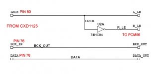
There has been posted this schematic to connect PCM56 to decoder, I have not tested it, but it should work. There will be l/r phase shift but that's not so bad for the beginning.
Attachments
Last edited:
If the nonos schematic was okay, then 470 ohm will be too high output, you can divide R by n and multiply C by n.
Yes, Bernhard, the schema I used was indeed OK to listen to, and I looked at a -60 dB track (1 kHz) and this still showed up as a sine-like curve (external triggering). The 0 dB was good too.
I will try the other schema and replace the 470 with 220 or so. And double the C to 3,9 nF or so.
As regards the phase shift in that schematic to connect PCM56, would this influence the stereo positioning?
albert
For 8x os 470 ohm // 2,2n or 1,8n. But I would remove the oversampling.
Did I post 22n anywhere ?
There has been posted this schematic to connect PCM56 to decoder, I have not tested it, but it should work. There will be l/r phase shift but that's not so bad for the beginning.
Hi Bernard,
Thanks for that NONOS schema.
I checked out the PCB and derived a schema, it would imply bridging connections on CXD2551 just almost done on the SAA7220:
- BCK_input from pin 76 on CXD2551 pin 6 goes to pin 13 - BCK_output and then on to the pin 5 CLK of both PCM56's.
- LRCK clock from pin 80 goes to pin 1 of the existing inverter chip and the output of the inverter pin 2 goes to R_LE (the right channel PCM56 pin 6) while this also goes to the the left channel PCM56 pin 6. The output on pin 8 of the string of three inverters is not used any more.
- DATA_input from pin 78 on pin 7 goes to both pins 15 & 16: DATA_L and DATA_R.
The MC74HCU04 inverter is already on the PCB, so this is easy, and there are three spare inverters. I'll use #1.
However I am a bit confused
 on the DATA. This is because the CXD2551 has a separate DATA_L and DATA_R output.
 I just want to check: is this correct, as far as IIS logic goes?
The CXD2551 datasheet (I refer to the CXD2550 datasheet) mentions:
* pin 15 called DATAR at 8fs (RCH serial data) but at 4fs it is WCK output
* pin 16 called DATAL is LCH data at 8fs but LCH+RCH time shared serial data when 8fs is selected.
Pin 2 is high (+5v) for the 8fs selection.
albert
Hi Bernhard,
Maybe you still follow this thread or maybe not.
I want to sincerely thank you for the patience you showed in giving advices and for your precious time.
Since our last posts, I finished a cathode follower buffer for my CDP, and I am impressed with the natural timbre and liveliness improvement from modern DAC, such as the akm4396.
THANK YOU!
pcm56
Hi, Dear, I have pcm56 in my cdP YAMAHA CDX 1000O ,
you could give me some advice on improving the sound of this player, I had thought of an output transformer for the DAC, and I wanted to bypass the opamp
that there are as output stage,
What do you think?
thanks luigi
Hi, Dear, I have pcm56 in my cdP YAMAHA CDX 1000O ,
you could give me some advice on improving the sound of this player, I had thought of an output transformer for the DAC, and I wanted to bypass the opamp
that there are as output stage,
What do you think?
thanks luigi
I can not follow you. Does it have the 1125 decoder ?
If yes, cut the 3 input traces of one PCM56 and connect as in the schematic and see if it works.
Maybe make a drawing of decoder, osfilter and dac for data, LE, bclk.
Luigi,Hi, Dear, I have pcm56 in my cdP YAMAHA CDX 1000O ,
you could give me some advice on improving the sound of this player, I had thought of an output transformer for the DAC, and I wanted to bypass the opamp
that there are as output stage,
What do you think?
thanks luigi
What you can do is take a resistor output, and amplify this with a tube stage.
I used a buffered output of a ECC88 with an anode load of 10K, kathode 220 ohm and 100 muF decoupling; [220 ohm could be lowered to 150-180 ohms, depending on Ra] ; and then a buffer of the other half of the tube with a 10K kathode load. Works like a charm and you get a natural roll-off of about 70-100 KHz. With a -80 dB trace I can just see the separate steps of the non-filtered output signal.
Note: ECC88 is designed for use as a cascode; in this design the pins 6/7/8 are for the input section; pins 1/2/3 are for the output buffer. The pins 123 have a higher filament to cathode rating of 150V!
I used a separate mains transformer with a 110V winding and used a simple buffer: TIP50 with a 47K resistor from + to the base, with a 22 muF connected from base to ground. Stops all noise from the mains, very effective. Crucial for low noise in the output. This would give about 110V DC.
Then you can tweek the load of the PCM56.
I started off with 423 ohm but later lowered to 110 ohms: enough for 2 V RMS out with the current tubes.
I did not do NOS. It is not my machine I worked on: I bought it for my nephew.
Now as regards the other elements:
I agree: throw out the opamps - but the filters are sometimes smart.
In my Philips (TDA1541A S1) I reused the filter components in a buffer section. This gives a natural sound with the designed roll-off that fits in with the oversampling and digital filter design. I used a Nelson Pass B1 stage and wrapped the sinx filter around it.
I have not used a transformer directly on the output.
albert
Last edited:
re- pcm56
Dear, Alber thanks for your reply,
see the diagram of my cdx 10000 with pcm 56 and tell me if and 'raccomadabile modify the outlet section and the filter, with a valve output or output transformer
or believe that the quality 'of the filter and' high and would not change with dramatic improvements,
What would you do?
thanks louis
Luigi,
What you can do is take a resistor output, and amplify this with a tube stage.
I used a buffered output of a ECC88 with an anode load of 10K, kathode 220 ohm and 100 muF decoupling; [220 ohm could be lowered to 150-180 ohms, depending on Ra] ; and then a buffer of the other half of the tube with a 10K kathode load. Works like a charm and you get a natural roll-off of about 70-100 KHz. With a -80 dB trace I can just see the separate steps of the non-filtered output signal.
Note: ECC88 is designed for use as a cascode; in this design the pins 6/7/8 are for the input section; pins 1/2/3 are for the output buffer. The pins 123 have a higher filament to cathode rating of 150V!
I used a separate mains transformer with a 110V winding and used a simple buffer: TIP50 with a 47K resistor from + to the base, with a 22 muF connected from base to ground. Stops all noise from the mains, very effective. Crucial for low noise in the output. This would give about 110V DC.
Then you can tweek the load of the PCM56.
I started off with 423 ohm but later lowered to 110 ohms: enough for 2 V RMS out with the current tubes.
I did not do NOS. It is not my machine I worked on: I bought it for my nephew.
Now as regards the other elements:
I agree: throw out the opamps - but the filters are sometimes smart.
In my Philips (TDA1541A S1) I reused the filter components in a buffer section. This gives a natural sound with the designed roll-off that fits in with the oversampling and digital filter design. I used a Nelson Pass B1 stage and wrapped the sinx filter around it.
I have not used a transformer directly on the output.
albert
Attachments
Luigi,
Certo . . . c'e raccomadabile
I like the output buffer Q603-610 but not the opamp before it, the stage around this opamp could be kept just deleting the opamp and connecting pins 4 and 2! Then the stock filter second stage works.
Try it and be marveled!
It works because the opamp amplifies 1*.
You can replace the IC610 with a simple B1 buffer (two FETS), or else go with the complementary pair with sources together . This latter is what I did to replace an opamp in such a 1* circuit.
Then all you need is a device to take the input from passive to the line level. Like I used a tube.
But in another CD I used the Nelson PASS I/V.
nota been: the output mute Q611-616 looks awkward to me.
albert
re- pcm56
Dear very thanks for your help ,
Please tell me step by step what I do (i am not a professional electronic only a fan)
1 ) Pins 4 and 2 are of 'Ic 608 and 607? ok?
2 Jump Ic 610 and go directly to Q604-606 ok?
Q611-Q616 and go bipass rca output by directly
..... and the last but I can take the signal from YM 3023 FSH and go directly to rca ouput?
thanks luigi
Luigi,
Certo . . . c'e raccomadabile
I like the output buffer Q603-610 but not the opamp before it, the stage around this opamp could be kept just deleting the opamp and connecting pins 4 and 2! Then the stock filter second stage works.
Try it and be marveled!
It works because the opamp amplifies 1*.
You can replace the IC610 with a simple B1 buffer (two FETS), or else go with the complementary pair with sources together . This latter is what I did to replace an opamp in such a 1* circuit.
Then all you need is a device to take the input from passive to the line level. Like I used a tube.
But in another CD I used the Nelson PASS I/V.
nota been: the output mute Q611-616 looks awkward to me.
albert
Dear very thanks for your help ,
Please tell me step by step what I do (i am not a professional electronic only a fan)
1 ) Pins 4 and 2 are of 'Ic 608 and 607? ok?
2 Jump Ic 610 and go directly to Q604-606 ok?
Q611-Q616 and go bipass rca output by directly
..... and the last but I can take the signal from YM 3023 FSH and go directly to rca ouput?
thanks luigi
Dear very thanks for your help ,
Please tell me step by step what I do (i am not a professional electronic only a fan)
thanks luigi
Take out the IC's first.
2 ) Pins 4 and 2 of 'Ic 609/610' can be connected and go directly to Q604-606. The initial part of the filter then feeds directly into the buffer. The feedback goes via the remaing C612 to the filter. Presto!
1) Pins 6 of Ic 609/610 would go to a PASS B1 pair (2SK170) input preferably in the DCB1 variant that is DC coupled. And pin 8 to the output of the buffer. If you use a fixed resistor that you have tested before, the Line Offset even works!!
0) Replace IC608 with a suitable amplification stage, such as a tube.
Now the trick: the output goes from PCM56 to the tube. Not via the YM 3023 FSH . You will have to make it in current out. The internal opamp of the PCM is used I guess.
It is now voltage out.
So bipass YM 3023 FSH - I think it is only signal logic such as mute.
The output is from the existing buffer stage Q603 etc like it is directly to the RCA plugs.
All by all, this looks like a nice implementation, very good shunt power supplies.
(As you understand i like puzzling)
albert
Hi,
it has a digital volume control.
Always set it to maximum volume to avoid quality loss.
It also has oversampling, opamp inside PCM56 is used for I/V, opamps for hf filter, sample & hold IC, all things that are not needed.
I have not tried to glue the PCM56 directly to the decoder IC, that would be the way to go.
If you start work inside the player, it could be a mess in the end.
Better only upgrade opamps or built an external DAC, it will not be more difficult.
re-pcm 56
thanks ,
Which Opamps can advise instead of NJM5532S - NJM4556S in my circuit?
luigi
thanks ,
Which Opamps can advise instead of NJM5532S - NJM4556S in my circuit?
luigi
Hi,
it has a digital volume control.
Always set it to maximum volume to avoid quality loss.
It also has oversampling, opamp inside PCM56 is used for I/V, opamps for hf filter, sample & hold IC, all things that are not needed.
I have not tried to glue the PCM56 directly to the decoder IC, that would be the way to go.
If you start work inside the player, it could be a mess in the end.
Better only upgrade opamps or built an external DAC, it will not be more difficult.
The internal OpAmp inside DAC is not that good, compared with modern OpAmps.
I like to use an external, better, OpAmp as I/V stage, but always use the INTERNAL laser-trimmed Rf resitor in the OpAmp feed-back loop (pins 10 and 13). In this way you maintain the factory trimming.
I cannot see a way to use that in a tube stage.
I like to use an external, better, OpAmp as I/V stage, but always use the INTERNAL laser-trimmed Rf resitor in the OpAmp feed-back loop (pins 10 and 13). In this way you maintain the factory trimming.
I cannot see a way to use that in a tube stage.
thanks ,
Which Opamps can advise instead of NJM5532S - NJM4556S in my circuit?
luigi
The usual suspects, opa627 on dual adapters ?
- Status
- This old topic is closed. If you want to reopen this topic, contact a moderator using the "Report Post" button.
- Home
- Source & Line
- Digital Line Level
- PCM56K iv resistor value?