BWRX said:Very nice work! Now put it to work in your power supply
I still have to build one for the other rail.

Just out of curiosity, how many 2n3055's do you think this circuit can handle? What would be the limiting factor? The current consumption of each base up to the LM317's limit?
theAnonymous1 said:What would be the limiting factor? The current consumption of each base up to the LM317's limit?
You got it. Darlington pass transistors could be used to further reduce the base current required from the LM317.
I saw your post and thought maybe I could figure out what I am doing wrong with my circuit. Ok, I am a total newbie, and I am having a hell of a time getting my voltage regulator working. I am not using any protection diodes, just the lm317 and 2 simple resistors.
I have a battery that is rated at 14.4v, but real world output is 16.8v at full charge. I want it at 13-14v so I don't short my amp. The resistors I have are 1k ohm and 100 ohm which in the equation I found yields 13.75v.
I figured the + input from the battery goes to the input pin, I have soldered the 100 ohm resistor to the input and adj pins. The 1k resistor goes to the adj pin, right? Am I correct in thinking that the adj pin is on the left, the output is in the middle, and the input pin is on the right? (Assuming the chip front with text is facing forward and the exposed back of the 317 is facing away)
So if I got that correct, then where does the negative input from my battery go, to which pin of the 317 should I connect it to? And the output pin should go to the + output correct?
I have tried following the schematic on the back of the package, but for the life of me I can't get it to work. Totally confused...
I can get my 41Hz amp 6 to work, I can make my own li-ion battery pack, but I can't seem to make a voltage regulator work. Oh well... maybe I got lucky with the amp and the battery. (its for my mp3 player and portable speaker system)
Anyway, any help would be immensely appreciated. If you have any suggestions feel free to email me. And my apologies if this has already been answered elsewhere, I just can't seem to find where that is.
jrodriguweb-next@yahoo.com
Hi,
have you downloaded the datasheet?
All the specifications and schematics are in there.
Sometimes it's worth looking at a few manufacturer's datasheets for little extras that only get included in a few.
The two resistors form a voltage divider from Voutput to 0v.
The junction of the two resistors connects to the adjustment pin.
You should also include a parallel capacitor from adjustment to 0v.
Check the datasheet to see if you need to add protection diodes.
YAY!!
I finally finished my supply, and it works!! I lost s few Toshiba 2N3055's along the way, but it was worth it.
I set the voltage at +-30V because with a 6R load the output from my transformer drops from 47V to 33V. Thats actually a good thing I guess, because the regulator only has to dissipate the other 3V @ 5A, which means my heatsink is way overkill. If I had a bigger trafo I could go up past 40V @ 10A.
At full load the voltage only drops about 0.5V at the output, so I'm pretty happy with it.
Thanks again to all that helped!
An externally hosted image should be here but it was not working when we last tested it.

theAnonymous1
I can see two bridge rectifiers used for two secondaries in the photo. These are not advisable as the current sharing in diodes is not good. Diodes in series or parallel are not advised. Better solution would be to parallel the secondaries and use a single proper current rated bridge rectifier.
Gajanan Phadte
I can see two bridge rectifiers used for two secondaries in the photo. These are not advisable as the current sharing in diodes is not good. Diodes in series or parallel are not advised. Better solution would be to parallel the secondaries and use a single proper current rated bridge rectifier.
Gajanan,
I'm new to electronics so I'm not going to pretend I fully understand what you mean. What I do know is that this symetrical supply is using two positive regulators which requires dual secondaries and seperate rectifiers. The 0v refference point is created after the regulation.
Thanks for whatever your warning be about though.

Hi Anon,
looking at the big pic you posted I think you have used mica insulators.
BUT
I cannot see any thermal conducting compound. Are you exceptionally neat and tidy?
Are the To3s in contact with that strip across the top of the cans?
Remember to insulate the bolts/screws holding the To3s to the angle.
Mica insulators need thermal compound on both sides to exclude air from the heat conducting joint.
Similarly the large aluminium angle bolted onto the heatsink will benefit from a compound coated interface (no insulator required).
Gmp,
if the bridges had been in parallel then the sharing solution was easy. The thick fairly short black wires from bridge to smoothing caps get replaced with longer and thinner cables. The inherent resistance in the long thin cables will force current sharing and act as a further attenuator for high frequencies due to resistance and inductance in the line to the RC filter.
Don't worry anonymous1, you have done it just right. gmphadte must have misunderstood something.
YES, from the picture it looked like the wires to the cap boards are shorted.
My apologies...
Gajanan phadte
Hi Andrew,
The insulators are Thermafilm, which is some kind of plastic(?). There is goop on both sides of the insulators just barely visible around the edges.
The 2N3055's are being "clamped" by the bars on top because I didn't have enough hardware to mount them by their flanges. The bolt in the middle is insulated from the bars by a nylon washer and heatshrink tube. I figured it would be easier to insulate two points instead of eight. I wasn't sure if passing current through the cans was a good idea, but it seems to work OK. Are they welded to the base?
I made a huge mistake my first go at the supply. When I etched the board for the caps I had both rails in series instead of seperate and ended up passing current the wrong way through the whole right side setup. It killed both the pass transistors.
Hi Anon,
you are confirming that the clamping plates are in contact with the To3 cases.
That means you can feed power into the collectors using the clamping plate in parallel to the bolted connection normally used. You do not need to insulate that screw from the plate. But I would clean the contact points and use petroleum jelly (Vaselin) to reduce corrosion and maintain clean contact.
AndrewT said:Hi Anon,
you are confirming that the clamping plates are in contact with the To3 cases.
That means you can feed power into the collectors using the clamping plate in parallel to the bolted connection normally used. You do not need to insulate that screw from the plate. But I would clean the contact points and use petroleum jelly (Vaselin) to reduce corrosion and maintain clean contact.
I am in fact doing this. I meant to say that it is insulated in a way as to not pass current from the bars to the angle stock through the bolt. If that did happen the positive rail would short out.
This is going to power a 41hz AMP1-B and will probably take me another month to finish everything.
Capacitor wiring...
This was suggested by the Guru Poobah in some thread
The two wires from the bridge rectifier to the filter capacitors should not be connected at one side but one of them should go to the other side(the last cap). This distributes the ripple to all the caps which would have been looked at by the first cap otherwise.
One end wiring stresses the first cap as it looks at the total ripple.
Gajanan Phadte
Thats pretty interesting, although it sounds a bit paranoid. I wonder what kind of real life effect it has.
Side note: Always make sure your chassis is big enough to fit everything you plan on putting in it. Looks like I'm going to have a fancy looking +-30v supply; with no amp inside.
Side note: Always make sure your chassis is big enough to fit everything you plan on putting in it. Looks like I'm going to have a fancy looking +-30v supply; with no amp inside.
Ask to calculate R to share CUrrent
Hallo anyone,
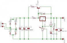
i'm want to ask how to calculate R1 and R2 to share Current.
i attackment the schematic
in this schematioc i want to increase current LM317 by using
TIP2955.
i want to increase current load about 2/3 ampere.
by share current in:
LM317 about 0.5 Ampere
and TIP2955 about 1.5 to 2.5Ampere. so the current handle by 2955
i watch many schematic but i still dont undrestand about calculate R1 and R2 to share current.
please help anyone becasuse i'm nebies and try to practice electronic.
please give me advise and reference to learn.
and i want to ask to.
D1 to D4 i change By IN5004
d5 and d6 should change to IN5004 to?
please help anyone.
sorry about my english.
Thanks
Hallo anyone,
i'm want to ask how to calculate R1 and R2 to share Current.
i attackment the schematic
in this schematioc i want to increase current LM317 by using
TIP2955.
i want to increase current load about 2/3 ampere.
by share current in:
LM317 about 0.5 Ampere
and TIP2955 about 1.5 to 2.5Ampere. so the current handle by 2955
i watch many schematic but i still dont undrestand about calculate R1 and R2 to share current.
please help anyone becasuse i'm nebies and try to practice electronic.
please give me advise and reference to learn.
and i want to ask to.
D1 to D4 i change By IN5004
d5 and d6 should change to IN5004 to?
please help anyone.
sorry about my english.
Thanks
Attachments
- Status
- This old topic is closed. If you want to reopen this topic, contact a moderator using the "Report Post" button.
- Home
- Amplifiers
- Power Supplies
- pass transistor in regulated supply?