I'm not fully understanding the need for the separate supplies.
I tried the circuit with both a single and dual supply and they both seem to model the same.
These both use a LM317 and are setup for how I need them; 45v in 35v out.
BTW, I know this is kinda like a kid bragging about riding his bike without trainings wheels, but this is the first time I've ever used a SPICE program or modeled any kind of circuit. Its kinda fun.
I tried the circuit with both a single and dual supply and they both seem to model the same.
These both use a LM317 and are setup for how I need them; 45v in 35v out.
An externally hosted image should be here but it was not working when we last tested it.
An externally hosted image should be here but it was not working when we last tested it.
BTW, I know this is kinda like a kid bragging about riding his bike without trainings wheels, but this is the first time I've ever used a SPICE program or modeled any kind of circuit. Its kinda fun.
You don't need separate supplies if the input-output voltage differential is high enough and you have adequate cooling for the devices. That link used separate supplies because that can allow the pass devices to operate more efficiently with less voltage drop across them.
LT spice is definitely fun to play around with
LT spice is definitely fun to play around with
So do the values in the first pic look OK to use? I have a pretty large heatsink these will be attached to.
The setup above seems to only be good for 10A, anything more than that and the supply looks like it completely collapses(prolly not the right term, just trying to sound smart ).
).
Brian, is there an "all-in-one" kind of combined SPICE library out there, or did you piece yours together? I had to search quite a bit just to get the single LM317 file.
The setup above seems to only be good for 10A, anything more than that and the supply looks like it completely collapses(prolly not the right term, just trying to sound smart
).Brian, is there an "all-in-one" kind of combined SPICE library out there, or did you piece yours together? I had to search quite a bit just to get the single LM317 file.
Your output current capability is basically limited by how much power you can dissipate in the pass devices and how much current the input can supply. If it's going to be a constant 10A then you'd need a really beastly transformer, rectifier, and filter caps. If it's more of a pulsed current draw then you can relax the transformer requirements a little bit and beef up the rectifiers and caps. Of course going ovekill never hurts anything but your wallet...
There's no all in one modle file that I know of. Linear Tech does a nice job of supplying a lot of components off the bat. They leave it up to you to find whatever else you may need. For simple component changes you can edit the files that contain the model data yourself.
There's no all in one modle file that I know of. Linear Tech does a nice job of supplying a lot of components off the bat. They leave it up to you to find whatever else you may need. For simple component changes you can edit the files that contain the model data yourself.
.SUBCKT LM117HV 1 2 3
IADJ 1 4 48.4U
VREF 4 3 1.2782
RC 1 14 0.742
DBK 14 13 DLM117HV
CBC 13 15 2.479N
RBC 15 5 247
QP 13 5 2 QLM117HV
RB2 6 5 124
DSC 6 11 DLM117HV
ESC 11 2 POLY (2) (13,5) (6,5) 2.85
+ 0 0 0 -70.1M
DFB 6 12 DLM117HV
EFB 12 2 POLY(2) (13,5) (6,5) 3.92
+ -135M 0 1.21M -70.1M
RB1 7 6 1
EB 7 2 8 2 2.56
CPZ 10 2 0.796U
DPU 10 2 DLM117HV
RZ 8 10 .104
RP 9 8 100
EP 9 2 4 2 103.6
RI 2 4 100MEG
.MODEL QLM117HV NPN (IS=30F BF=50
+ VAF=14.27 NF=1.604)
.MODEL DLM117HV D (IS=30F N=1.604)
.ENDS LM117HV
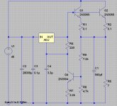
OK, I changed the values of the resistors to values I have. R9 will be a trim pot.
Is there anything wrong with this or anything I should add or change? If not, I'm going to go ahead and build it .
Here's the simulation file.
Is there anything wrong with this or anything I should add or change? If not, I'm going to go ahead and build it .
An externally hosted image should be here but it was not working when we last tested it.
Here's the simulation file.
Attachments
I can't simulate it with the 317 because it says I don't have the 317 symbol, but those values look like they should work. Be careful of the power dissipation in some of the resistors. I only checked it for the values I used in my schematic. I ran some numbers quick and everything looks fine. You can change the values of R7, R8, and R9 if you don't have the values used in the schematic.
I would also add a 1uF or so cap between the adjust pin and ground. Make sure it has an adequate voltage rating. You may also want to add a protection diode between the adj pin and vout like in the standard LM317/338 circuits.
I would also add a 1uF or so cap between the adjust pin and ground. Make sure it has an adequate voltage rating. You may also want to add a protection diode between the adj pin and vout like in the standard LM317/338 circuits.
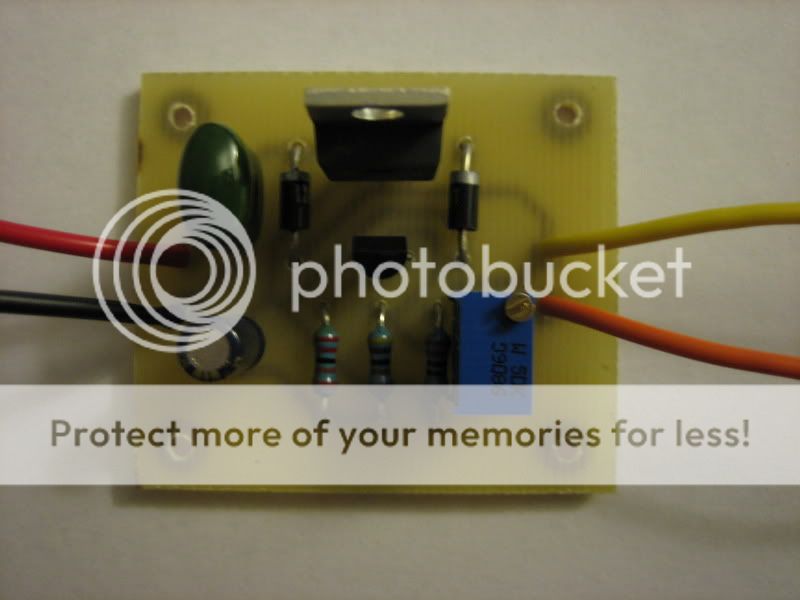
Hey fellas, I need a bit more help. I built a test circuit but something is wrong. Its the exact same circuit as the one I posted above but with 2 protection diodes.
The circuit regulates the voltage and I can adjust it with the trim pot I have for R9, but after about 20 seconds or so R7 starts to glow orange and Q4 dies.
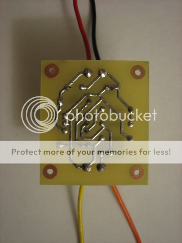
Here is a pic of the board....
http://i9.tinypic.com/2jctq2u.jpg
The circuit regulates the voltage and I can adjust it with the trim pot I have for R9, but after about 20 seconds or so R7 starts to glow orange and Q4 dies.
Here is a pic of the board....
http://i9.tinypic.com/2jctq2u.jpg
You're using a 317 or 337 right? And the output voltage is around 35V? With the values in your schematic?
The 1.25V across R4 (100ohm) sets the current through Q4 to be about 12.5mA. The output voltage is set to about 35V so the voltage at the output of the 317 will be around 36V and the voltage at the collector of Q4 will be about 34.75V. 12.5mA through R7 (47ohm) will have the emitter of Q4 at about 0.6V. That means there is about 34.15V across Q4 with 12.5mA flowing through it, meaning it has to dissipate about 0.43W! Try putting a resistor in series with the collector of Q4. I would use a 1/4W resistor around 1kohm to 1.2kohm for your 35V output voltage. Be careful of the dissipation in the trimpot you're using too. It should be 1/8W minimum with the values you're using that schematic.
The 1.25V across R4 (100ohm) sets the current through Q4 to be about 12.5mA. The output voltage is set to about 35V so the voltage at the output of the 317 will be around 36V and the voltage at the collector of Q4 will be about 34.75V. 12.5mA through R7 (47ohm) will have the emitter of Q4 at about 0.6V. That means there is about 34.15V across Q4 with 12.5mA flowing through it, meaning it has to dissipate about 0.43W! Try putting a resistor in series with the collector of Q4. I would use a 1/4W resistor around 1kohm to 1.2kohm for your 35V output voltage. Be careful of the dissipation in the trimpot you're using too. It should be 1/8W minimum with the values you're using that schematic.
Those values should work nicely, and will give you about 33V at the output. They lower the overall dissipation as well as spread it around more evenly. Hopefully you won't have any more transistor casualties  None of the resistors should get hot with the values you chose and most of the dissipation will still be handled by Q4.
There's no "putting up with" going on here! I'm anxious to hear how it works too
That's a nice and clean little protoboard circuit you made too. Good stuff
None of the resistors should get hot with the values you chose and most of the dissipation will still be handled by Q4.There's no "putting up with" going on here! I'm anxious to hear how it works too
That's a nice and clean little protoboard circuit you made too. Good stuff
Oh boy, I seem to have overlooked something VERY imoportant..... the pinout of an LM317.
I've never used an LM317 or any other adjustable regulator before and I was going by how the pins are arranged in the circuit from left to right. Silly me.
Oh well, live and learn.
EDIT: I just tried the circuit with the last posted values and it works great now that I have the pins correct. At full load none of the components except the 2N3055 get hot.
I would say that was a good 5 hours wasted because of a stupid mistake, but I'll just take it as a lesson learned. Thanks for all your help Brian. I'll post a pic of the whole supply when its all together
Ah, it's always the simple things. It happens to the best of us. It happens all the time at work. The soldering guy builds a board, the inspector guy looks the board over and says everything looks ok, the software guy tries to flash the micro and can't figure out why the thing won't work. A couple hours later, lots of head scratching, and troubleshooting and we see that one tiny chip that sets some conditions for external memory is on backwards.... We reorient it and viola, fires up first try. Whenever something doesn't work that's the first thing I look for anymore. That and making sure everything is connected properly... lots of headaches from stuff like that too. Anyway, good to hear the supply is up and running
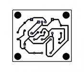
I think I'm gonna skip the proto board and go for the real deal. I've never etched a PCB before, but I have a ton of PCB stock I purchased for a non-electronics purpose. I also have access to laser printers, photo paper, a metal shear, and ferric chloride at work (etching/lithography/photo lab).
Here is my first attempt at using a PCB design program.
Here is my first attempt at using a PCB design program.
Attachments

- Status
- This old topic is closed. If you want to reopen this topic, contact a moderator using the "Report Post" button.
- Home
- Amplifiers
- Power Supplies
- pass transistor in regulated supply?