luka said:Hi
First of all you shouldn't use R2, R1= 0.7v/I(stabilizator)
it share the current to transistor and LM317 to luca?
please give me reference to learn.
i try to use input ac abot 15VAC and output dc15V
thx
thank very much luka.luka said:Hi
R1= Ube(0.7v)/I(stabilizator= 0.5A)
When 0.5A will go into stabilizator, there will be 0.7v voltage drop on R1, and transistor will start to open/conduct
Doesn't depend on input/output voltage, only current
i will try your advice and reference.
i try to build regulator op amp but the problem is in current.
sory about waste your time.
thank.
Hi
Hey no problem...You won't have limited current for PNP, only for LM. If you would want to limit for PNP too, you would need to add NPN and one resistor. So you would have 2 resistors, 2 transistors, and anything that LM needs
Similar of what I think is here, on page 16
Hey no problem...You won't have limited current for PNP, only for LM. If you would want to limit for PNP too, you would need to add NPN and one resistor. So you would have 2 resistors, 2 transistors, and anything that LM needs
Similar of what I think is here, on page 16
luka said:Hi
Hey no problem...You won't have limited current for PNP, only for LM. If you would want to limit for PNP too, you would need to add NPN and one resistor. So you would have 2 resistors, 2 transistors, and anything that LM needs
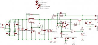
im try to build this opamp reg luca
for playing asuscd52X
need 5V 1.2A
and 1.5 12V
whit that circuit, can i change BD241 with TIP2955 to?withut any modif?
please give me advice luca
because in normal play 2 regulator +5 +12 the bd241 is hoot, lm317 toooo. event i change by lager heatsink.
with add 2955 wityh your advice,
can i change bd 241 so that op amp regulator can work in 1.5 - 2A current load.
thank luka
Attachments
luka said:Hi
aaa why don't you just use 2x LM7812 and 2x LM7805 and small resistors, 0.1R after each for current sharring?
And if you can use lover Vac, say 12V, which will give ~16v
thge quality of regulator effect the sound luka,
my friend is try to use that reg with 5V to chgange usb voltage to usb soundcard the sound quality is so different luka.
in my oppinion. lm 317 is more stabil than 78X luka,
that schematic base on sylzer bobbely regulator,
now the favorite is jung regulator, but in my country is very difficult to
search komponent luka
Full Regulation?
hi all,
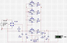
sorry for being newbie in elec and regulators but i want to ask somthing, i have about 10 regulators "LM338T & LM138T" and transformer 220v To 12-0-12 @ 8Amps i have read the LM338 Datasheet and tried to make variable regulator without pass transistor as LM338 can handel about 5A and i need to draw only 4A@20v max but the problem is that the voltage drops low about 10 volts at full load "20v@4A" so please any one help me , i've read all that threat from start but i was unable to figure out how theAnonymous1 was able to get voltage drops only 0.5v at full load?, i even try to parallel about 4 LM338 but it was not enough voltage still drop about 8 volts so all that for 2 volts recover?!, i hope any one tells me what to do to maintain voltage at full load, and also here is my circuit to analyze if there any thing wrong plz tell me, also is it really that LM138 Is Better Than LM338?!
hi all,
sorry for being newbie in elec and regulators but i want to ask somthing, i have about 10 regulators "LM338T & LM138T" and transformer 220v To 12-0-12 @ 8Amps i have read the LM338 Datasheet and tried to make variable regulator without pass transistor as LM338 can handel about 5A and i need to draw only 4A@20v max but the problem is that the voltage drops low about 10 volts at full load "20v@4A" so please any one help me , i've read all that threat from start but i was unable to figure out how theAnonymous1 was able to get voltage drops only 0.5v at full load?, i even try to parallel about 4 LM338 but it was not enough voltage still drop about 8 volts so all that for 2 volts recover?!, i hope any one tells me what to do to maintain voltage at full load, and also here is my circuit to analyze if there any thing wrong plz tell me, also is it really that LM138 Is Better Than LM338?!
Attachments
an 8Aac transformer feeding a capacitor input filter must be de-rated to ~ 70% of it's VA rating.
When you apply the sqrt(2) factor to the output voltage you end up with the maximum continuous DC current ~ AC current / two.
If you draw 4Adc from the regulator the transformer will be running at it's maximum rating. It will run hot.
We usually recommend that the continuous DC current be reduced to <half that maximum, i.e. 2Adc for cool running.
You have 2*4.7F smoothing capacitance. Have you calculated the ripple voltage on these caps when drawing 4Adc?
Have you measured the maximum voltage on the smoothing caps when the load increases to 4A?
You must subtract the full peak to peak ripple voltage from the maximum voltage at the smoothing caps. What voltage is left?
That is what is feeding the regulator.
What is the drop out voltage of the single regulator when passing 4Adc?
Take this off and what you are left with is the MAXIMUM voltage available from your power supply. You must arrange for the resistor ladder that defines the output voltage to be LESS than that maximum output voltage.
Have you measured the mains voltage at the input to the transformer?
Does it change as you increase the output current of the regulator?
Does your mains voltage change throughout the day and week to week?
thanks for reply Andrew, I'm quit beginner to full understand some of your explanation i hope to clear them for me :
Do you mean that the max DC Amps i can draw after capacitor input filter is 4A? , and what is VA rating and sqrt(2) factor?
well using only one regulator and drawing 2 A @ 20v Voltage drops to about 17v , And between filter capacitor terminals it drops from 35v to 25v
I'm afraid i don't know how to do such calculates I'll be thankful to tell me how to do it, but i thought that 2*4.7F smoothing capacitance is more than enough @4A draw, Am i wrong?
Already done, my transformer output is about 35vdc and i limit output voltage to 20v
transformer input is stable at 210vac, little changes max "1 or 2 volts up or down" and main voltage doesn't change as we use 5k stabilizer on the main line of house.
another thing, if all calculations are okay, does it suppose with such circuit to provide stable 20v@4A with out voltage drop?, or can i use transistor as reference amplifier at adjust pin to improve regulation?
and thanks all ...
an 8Aac transformer feeding a capacitor input filter must be de-rated to ~ 70% of it's VA rating. When you apply the sqrt(2) factor to the output voltage you end up with the maximum continuous DC current ~ AC current / two.
Do you mean that the max DC Amps i can draw after capacitor input filter is 4A? , and what is VA rating and sqrt(2) factor?
We usually recommend that the continuous DC current be reduced to <half that maximum, i.e. 2Adc for cool running
well using only one regulator and drawing 2 A @ 20v Voltage drops to about 17v , And between filter capacitor terminals it drops from 35v to 25v
You have 2*4.7F smoothing capacitance. Have you calculated the ripple voltage on these caps when drawing 4Adc? Have you measured the maximum voltage on the smoothing caps when the load increases to 4A? You must subtract the full peak to peak ripple voltage from the maximum voltage at the smoothing caps. What voltage is left?
I'm afraid i don't know how to do such calculates I'll be thankful to tell me how to do it, but i thought that 2*4.7F smoothing capacitance is more than enough @4A draw, Am i wrong?
You must arrange for the resistor ladder that defines the output voltage to be LESS than that maximum output voltage.
Already done, my transformer output is about 35vdc and i limit output voltage to 20v
Have you measured the mains voltage at the input to the transformer? Does it change as you increase the output current of the regulator? Does your mains voltage change throughout the day and week to week?
transformer input is stable at 210vac, little changes max "1 or 2 volts up or down" and main voltage doesn't change as we use 5k stabilizer on the main line of house.
another thing, if all calculations are okay, does it suppose with such circuit to provide stable 20v@4A with out voltage drop?, or can i use transistor as reference amplifier at adjust pin to improve regulation?
and thanks all ...
The VA rating of your transformer is [12+12] * 8 = 192VA
This must be de-rated to 60 to 70% when feeding a capacitor input filter. Your 192VA becomes ~134W.
The sqrt(2) factor is the voltage peak of an AC waveform.
12+12Vac becomes 33.94Vpk, call it 34Vdc after the rectifier and smoothing caps.
The current available is power / voltage = W / Vdc = 134 / 34 = 3.94Adc.
That is the maximum continuous current available from your 12+12 8A transformer, i.e. ~half the AC current rating.
no,redfox750 said:drawing 2 A @ 20v Voltage drops to about 17v , And between filter capacitor terminals it drops from 35v to 25v.................................
Already done, my transformer output is about 35vdc and i limit output voltage to 20v
you confirm that the average voltage @ zero output current is 35Vdc and this includes the low peak to peak ripple when drawing a tiny current to power the regulator.
You also confirm that the average voltage falls to 25Vdc when passing 2A to the output. This now includes a quite large peak to peak ripple. Half that ripple voltage (Vpk) must be subtracted from the 25Vdc to see what the minimum voltage is before the regulator.
You must also subtract the drop out voltage for the 2A output current.
I suspect the maximum regulator output, at 2A, with your set up is <=21Vdc. If your mains drops by 6% at times of high demand then you can expect the maximum output to be even lower.
Your 24V 8A transformer cannot give 2A @ 20Vdc, never mind trying to get 4A @ 20Vdc.
However,
there is something else wrong.
The voltage should not drop from 35Vdc to 25Vdc when drawing 2A.
I would expect better than 30Vdc @ 2A.
check your circuit, check your wiring, check everything you are able to.
Ripple voltage on the capacitor fed supply.
1Farad supplying 1Ampere will lose 1Volt every 1second.
You have 0.0094F, 2A current draw and the mains repeats the recharge every 0.01s (50Hz).
Your peak to peak ripple is ~2 / 0.0094 * 0.01 ~=2.1Vpp.
Sorry Andrew but I'm sure there is something else isn't write even after i followed the calculates and using 2x10000uF capacitors voltage still drops, even when draw 200mA@12v only, voltage drops at least 2volt, that's too bad regulation, i think it's something with LM338 itself my guess is that LMxxx regulators quality isn't good enough using the basic circuit so that voltage drops even in low current load, that's why the great LM317 drops about 2volts too at "12v@200mA" isn't there any one who was able to develop the basic circuit to effectively compare output voltage and stabilize the voltage with very low drop?, i wonder what the theAnonymous1 did to get only 0.5volt drop at high load
- Status
- This old topic is closed. If you want to reopen this topic, contact a moderator using the "Report Post" button.
- Home
- Amplifiers
- Power Supplies
- pass transistor in regulated supply?