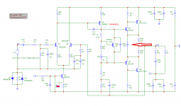
Whilst a lot of AndrewT's criticism applies no less to the original ESP P3a design, using 2SB649 for the VAS transistor could be an issue, if they were genuine Hitachi, not as the faked logo on currently available parts suggests. I think we should be aware that Renesas made these obsolete some 12 years back when they moved out of Japan and axed most smaller discrete components from the old Hitachi range......2sb649 for Q4 is crap. Use a low Cob with as high a gain+fT as you can afford......The low Cob for Q4 may require C5 to be increased, start with 100pF and reduce until you see excessive overshoot on a 1kHz sqwave.
Try adding a 50k VR in series with C7 5p6F and use that in combination with C5 to trim the overshoot....
Exact parts types are not always critical but VAS and even driver transistors do tend to be. I think we should look at what parts we have used and where we bought them, saying in advance of posting evaluation results, that our parts quality is at least doubtful.
So unfortunately, we can't rely on specifications. Cob is seldom quoted by 2nd sources and is not simple to measure. I make simpler direct measurement of Ccb instead and this allows a relative comparison to known quality parts but this not really correct. That's a pity for a quality emphasized so much here, whether it is super-low Cob for SOTA technical perfectionist designs or medium in designs intended for listening pleasure, like this one

..but the thing is in my actual build DC offset is way too high ( measured at 112mv) I find it odd...
Attached Thumbnails
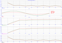
another simulation to actual world reality.....
without input ltp emitter degeneration resistors, you are obliged to match the input ltp trannies for equal Vbe and hFE at the desired collector current....
leach showed how to do it....The Leach Amp - Part 2
Whilst a lot of AndrewT's criticism applies no less to the original ESP P3a design, using 2SB649 for the VAS transistor could be an issue, if they were genuine Hitachi, not as the faked logo on currently available parts suggests. I think we should be aware that Renesas made these obsolete some 12 years back when they moved out of Japan and axed most smaller discrete components from the old Hitachi range.
Exact parts types are not always critical but VAS and even driver transistors do tend to be. I think we should look at what parts we have used and where we bought them, saying in advance of posting evaluation results, that our parts quality is at least doubtful.
So unfortunately, we can't rely on specifications. Cob is seldom quoted by 2nd sources and is not simple to measure. I make simpler direct measurement of Ccb instead and this allows a relative comparison to known quality parts but this not really correct. That's a pity for a quality emphasized so much here, whether it is super-low Cob for SOTA technical perfectionist designs or medium in designs intended for listening pleasure, like this one
i use npn video output trannies harvested from crt pc monitors, but they are now disappearing fast....
Yes, actual parts used could be an issue and will have the bigger impact to measured results, with simulation, device models is of course the ideal.
Honestly, I do not want to add more parts because the possibility is endless and will make the design move farther away from the P3A topology. I've read a lot with this topology CFP (as emitter follower). I keep on encountering from user's feedback that it sounds quite different. In simulation you can see that this simple design is able to display a nicely balanced current spread all over the entire circuit. (with a few adjustment here and there if not using the suggested parts)
Honestly, I do not want to add more parts because the possibility is endless and will make the design move farther away from the P3A topology. I've read a lot with this topology CFP (as emitter follower). I keep on encountering from user's feedback that it sounds quite different. In simulation you can see that this simple design is able to display a nicely balanced current spread all over the entire circuit. (with a few adjustment here and there if not using the suggested parts)
I've added some of Andrew T's suggestion, run it in sim and transient spikes at 30khz was gone. It is quite surprising the key is in the ltp degenerators. In the actual test dc offset is now measured a low 3mv. Amp is still dead silent and still sounds P3A like.
I am curious though with the attached e-lytic cap at the driver emitters, because comparing it with the plain P3A, at around 20ma quiescent current and played music for an hour the one with the attached e-lytic shows a slow cooling effect in the heatsink than the plain P3A, but driver heatsink is more warmer than the plain P3A. I've been browsing the internet for a reference but I can't find one. There is no mention of it in D.Self's book, I think it was the post of member Stee that explains it to be an aid in output bias current stability and thus preventing the amp to self oscillate.
Any more theory behind. Anyone?
Thanks!
Attachments
I've added some of Andrew T's suggestion, run it in sim and transient spikes at 30khz was gone. It is quite surprising the key is in the ltp degenerators. In the actual test dc offset is now measured a low 3mv. Amp is still dead silent and still sounds P3A like.
I am curious though with the attached e-lytic cap at the driver emitters, because comparing it with the plain P3A, at around 20ma quiescent current and played music for an hour the one with the attached e-lytic shows a slow cooling effect in the heatsink than the plain P3A, but driver heatsink is more warmer than the plain P3A. I've been browsing the internet for a reference but I can't find one. There is no mention of it in D.Self's book, I think it was the post of member Stee that explains it to be an aid in output bias current stability and thus preventing the amp to self oscillate.
Any more theory behind. Anyone?
Thanks!
that cap is a bypass cap, at dc the emitter resistors stabilises bias,
at ac output stage transconductance is higher because of it...
Hi!
It is one of my favorites, I like small ciruits with sonic wonders, like VHex VSSA Circlophone
I also rode the VSSA (peeceebee) and enjoyed the sound.
I'm curious about the sound of P3A.
Thanks!
Hi Sir Tony,
Is this good and something beneficial to the design? I cannot confirm if it shows an effect in sonic quality, it is fairly large though. In sim a small value will not work in eliminating transient spikes at higher freq. EF type II output has it too but in a smaller value in parallel with a resistor.
Is this good and something beneficial to the design? I cannot confirm if it shows an effect in sonic quality, it is fairly large though. In sim a small value will not work in eliminating transient spikes at higher freq. EF type II output has it too but in a smaller value in parallel with a resistor.
I also rode the VSSA (peeceebee) and enjoyed the sound.
I'm curious about the sound of P3A.
Thanks!
Build it and you will not be disapppointed, you can find a lot of shared pcb for DIY home etching in this forum or design one to your liking.
Better yet get the boards from Rod Elliott.
.
Hi Sir Tony,
Is this good and something beneficial to the design? I cannot confirm if it shows an effect in sonic quality, it is fairly large though. In sim a small value will not work in eliminating transient spikes at higher freq. EF type II output has it too but in a smaller value in parallel with a resistor.
try it both ways and see which way you like better....
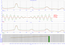
After a few more simulation run and actual testing, it seemed the basic circuit is still the better one. The design is one hard to crack and patch a few parts addition and still get nice results. Maybe it could be done by going into complexities by redesigning each stages which means going out of P3A bounds.
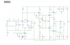
Anyhow, I came up with this circuit still keeping the basic with a few basic parts addition...I'm not so good with interpreting the simulated results, Is this good or something went bad?
Thanks!
Anyhow, I came up with this circuit still keeping the basic with a few basic parts addition...I'm not so good with interpreting the simulated results, Is this good or something went bad?
Thanks!
Attachments
Member
Joined 2009
Paid Member
input ltp degeneration resistors decreases the transconductance of the input ltp, but linearizes it.....
If you don't want to change the open loop gain (which would be another departure from P3A original ?) then the usual approach when adding emitter degeneration to the LTP is also to increase the tail current to bring the transconductance back up to where it was before degeneration. IIRC you need an extra 1mA for every 25Ohms ?
The improvement in linearity is still there - and most important is the improvement in linearity for peaks in the signal as it flattens out the whole LTP curve.
Strange choice for Q9 (Vbe), it's a high voltage TO-92 part. You'd be better off with a TO-126 part for bolting to a driver device for thermal management. And ideally the Vbe device would be a high-beta device that's happy to operate with a low voltage across it. What's wrong with the BD139/140 family ?...Anyhow, I came up with this circuit
Last edited:
If you don't want to change the open loop gain (which would be another departure from P3A original ?) then the usual approach when adding emitter degeneration to the LTP is also to increase the tail current to bring the transconductance back up to where it was before degeneration. IIRC you need an extra 1mA for every 25Ohms ?
The improvement in linearity is still there - and most important is the improvement in linearity for peaks in the signal as it flattens out the whole LTP curve.
all a matter of operating points choice, degeneration decreases gain but increases bandwidth.....
can't increase tail current very much higher for noise considerations.....here, simulations helps...
Member
Joined 2009
Paid Member
Hi Bigun,
I was thinking, a to-126 device for the vbe multiplier seemed to be larger for use in this circuit.
Its the larger size that makes it easier to handle - its the most common size for Vbe as far as I know.
Member
Joined 2009
Paid Member
all a matter of operating points choice, degeneration decreases gain but increases bandwidth.....
can't increase tail current very much higher for noise considerations.....here, simulations helps...
I never thought about noise before, at least the issue with higher tail current instead seems to me to be related to having use a smaller collector load which reduces OLG.
Could also try a collector load on Q2 to balance Vc at both ltp devices - neve tried it myslf but SandyK of years past said it kept the Early Effect matched when he was tweaking the AKSA amplifier.
Last edited:
- Home
- Amplifiers
- Solid State
- P3A-More upgrades