Hi Sir Tony,
That overshoot starts to appear at >30Khz only, for the lower frequencies it is not evident. While rearranging the feedback network and or the input bandpass filter, that overshoot can be eIiminated. it does have an impact in gain and DC offset. For example I could set the gain at 20db and the overshooting is gone but offset gets a little higher which means adjusting the ltp values, but 20db is a little low I guess.
My circuit is becoming smaller by omitting some parts and is all PNP now (because I have more of them than the NPNs). I do think my brain is messed up by reading more papers in the CFP implementaion, because some theorys/studies does not seem to agree with what I have read from our experts here. For example there is this paper that mentions "pull out" resistor at the driver bases is not necessarily needed since it senses the drivers only so the emphasis is to make a good bias circuit....another one states that the drivers does not need more current to drive the outputs to their linearity about 2-6ma should be enough. (P3A has it at around 2-3ma.)
I may have to start a new thread but I'll give it a thought first...there are plenty to read out there, knowing the right one is a tug of war")
That overshoot starts to appear at >30Khz only, for the lower frequencies it is not evident. While rearranging the feedback network and or the input bandpass filter, that overshoot can be eIiminated. it does have an impact in gain and DC offset. For example I could set the gain at 20db and the overshooting is gone but offset gets a little higher which means adjusting the ltp values, but 20db is a little low I guess.
My circuit is becoming smaller by omitting some parts and is all PNP now (because I have more of them than the NPNs). I do think my brain is messed up by reading more papers in the CFP implementaion, because some theorys/studies does not seem to agree with what I have read from our experts here. For example there is this paper that mentions "pull out" resistor at the driver bases is not necessarily needed since it senses the drivers only so the emphasis is to make a good bias circuit....another one states that the drivers does not need more current to drive the outputs to their linearity about 2-6ma should be enough. (P3A has it at around 2-3ma.)
I may have to start a new thread but I'll give it a thought first...there are plenty to read out there, knowing the right one is a tug of war
Member
Joined 2009
Paid Member
The CFP has many interesting things to learn about that aren't always clear until you build and play - for example, in my TGM8 amplifier I took the P3A as a starting point and redesigned every element of it for better performance. The prototype CFP output produced shoot-through on my scope until I learned how to solve that by setting the driver current at an appropriate level.
That overshoot starts to appear at >30Khz only
i am not even sure if this is an issue...
maybe what you can do is to choose devices with higher fT's than what you have now....
Hi Gareth, that must have been a worrying development. Can you make a simple summary of what you did different to P3a in your prototype to cause cross-conduction and what did you change to eliminate it?....The prototype CFP output produced shoot-through on my scope until I learned how to solve that by setting the driver current at an appropriate level.
Post 75
Hi abetir.
What do you think about this modification in your schematic.
a) LTP: the 22K collector resistor for Q2 (like NAP140), Nigel Pearson says "It raises the second harmonic to give warmth and give correct harmonic balance".
b) No miller cap in the VAS, use a RC filter in the input VAS (like Arcam A60).
thanks
Attachments
the R+C across R6 is a stability correction for the collector load of the Input LTP.
It is not an RC filter to the VAS input.
Many British power amplifier Designers did not use Cdom (Miller comp) and used stability components in other locations.
Why would anyone corrupt the performance of the power amplifier? Make the power amplifier work properly.
If the user requires EQ, then apply that in a dedicated EQ contraption that the user can insert, or throw in the bin.
Last edited:
used in many tube designs, the mullard 5-20 comes to mind, a British design....the R+C across R6 is a stability correction for the collector load of the Input LTP.
i use that trick in my tube amp builds....
R 22k in the collector unbalances the Vce of the LTP.AndrewT
That thing is corrupt? R22K in the LTP or RC shuntcomp in the VAS?
Balance the LTP.
...does someone here know where can i buy 2 PCB for the P3A ?
Thanks
ask Rod Elliott
Hi
Another way a resistor connected the output to the top of the LTP, modulating the current in step with the signal applied to the bases of the LTP transistors. This results in some creation of harmonic distortion, primarily 2nd order.
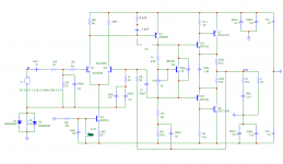
TGM6 schematic (Bigun). LTP input, no miller cap in the VAS (with R+C shuntcomp), EF output.
Conclusion: TGM6 with CFP output.
What are your opinions?
Another way a resistor connected the output to the top of the LTP, modulating the current in step with the signal applied to the bases of the LTP transistors. This results in some creation of harmonic distortion, primarily 2nd order.
TGM6 schematic (Bigun). LTP input, no miller cap in the VAS (with R+C shuntcomp), EF output.
Conclusion: TGM6 with CFP output.
What are your opinions?
Attachments
Hi abetir.
What do you think about this modification in your schematic.
a) LTP: the 22K collector resistor for Q2 (like NAP140), Nigel Pearson says "It raises the second harmonic to give warmth and give correct harmonic balance".
b) No miller cap in the VAS, use a RC filter in the input VAS (like Arcam A60).
thanks
Hi Geirin,
Hi haven't played with harmonics in sim. I thought this is some sort of a preference. I am currently working with intermodulation because this is where the controversial 100pf at the output , evident. Some analyst dislike it and labelled it as "sonic killer". Rod mentioned it as a compensation to kill the occuring parasitic oscillation at the negative rail.
This is how I see it parasitic oscillation will likely to occur at higher freq. in the negative rail, simulated transient response shows it.The culprit is in the riding frequencies. I came across the idea of converting the Vas trannie into an NPN one so that VAs cdom will be in line with the base of the negative rail driver but a small degenerator at VAS emitter is needed to prevent rail sticking ( a possible problem).
It is curious how this nice circuit resist to any tentative to "upgrade" it, every enhancement trick that is effective on a blameless type amp, here is non influent, or worse, the circuit reacts badly. Only thing that seems to work is reversing the sexes of LTP and VAS, it works Ok but not better than the original; and at this point it is no more a P3a, but another thing ... fortunately I amorously saved an original Rod Elliot board, that I will populate when I finally get tired of playing with LTSpice
Last edited:
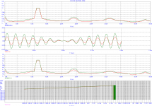
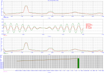
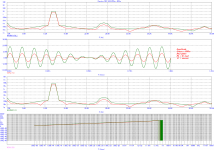
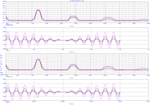
....was trying to upload the IMD results of the plain P3A, Ranchu's mod and David Bucci's mod but i am being abruptly disconnected from the net...slow access here
That's very interesting , please upload it.
Thanks
Simulated results is made using the same device models (BD/BC) on all circuits with the same quiescent current condition.(30ma) Slone's IMD is for reference only.
Attachments
- Home
- Amplifiers
- Solid State
- P3A-More upgrades