Member
Joined 2009
Paid Member
I started with ceramic Miller caps and later changed them to silver mica.
Interesting - can you remember, were they the same value ? Did you use npo/cog ceramic (good) or something else (baaaad) ? did you hear a difference between them ?
As said one of the P3A i made was constructed with """anything i can find parts "" that will be 3055-2955 outs 139-140 drivers and classic ceramics of 100pf equally the Ltp and current source was also anything available '
Both measuring and listening was by far worst distortion and bandwidth figures had a difference of at least 30% worst .
At that point the race was against a pcb that had properly matched LTP and mica caps that should be like 5-6 years ago later on with better choice of parts , matched drivers and a better VAs things got even more better than the """"anything i have """"project
Kind regards Sakis
The intention of the project was to know first hand what a poor choice of parts can do to a known amplifier .-
Member
Joined 2009
Paid Member
I see. Well, I guess my question was really about the possibility of identifying the effect of only one change
I believe there has developed an allergic reaction by people to use of ceramic because of historical use of poor ceramic, especially by cheap manufacturers. They did not use the excellent npo/cog types. These types have better performance than many other types of capacitors but are still shunned by some people. So the question is still specifically about this ceramic.
I noticed you changed your username Sakis")
I believe there has developed an allergic reaction by people to use of ceramic because of historical use of poor ceramic, especially by cheap manufacturers. They did not use the excellent npo/cog types. These types have better performance than many other types of capacitors but are still shunned by some people. So the question is still specifically about this ceramic.
I noticed you changed your username Sakis
yes about the name ... Its better for Google to find me easier ....
As about the rest ..i am sorry to say that is almost a year now that i didn't produce a new pcb for the P3A or tested any goodies like the degeneration and a few others i have in mind ..
Sorry for that but god i am so busy that i come to work 6 days a week something like 9.00 and go from the lab often after 12.00 midnight ...
Too much work ...
Kind regards
Sakis
Member
Joined 2009
Paid Member
No such thing as too much work when you are self-employed, it is a good sign for your bank manager and then you can buy some fine wine
I am still very attracted to this amplifier and perhaps I should be the one to make a new pcb. I will include some goodies if I do this. Would this amplifier be a candidate for my home theatre ? could it really compete with the SKA GB150 from Greg Ball ? it might be interesting for me to find out.
I am still very attracted to this amplifier and perhaps I should be the one to make a new pcb. I will include some goodies if I do this. Would this amplifier be a candidate for my home theatre ? could it really compete with the SKA GB150 from Greg Ball ? it might be interesting for me to find out.
Same here. Mostly I just lurk here, but I would be interested in seeing what you come up with.I am still very attracted to this amplifier and perhaps I should be the one to make a new pcb. I will include some goodies if I do this.
I built mine using the boards from the ESP web site, and I made some of the changes that were suggested by Sakis. Some are not very easy using the original boards, like on-board caps which are much larger than the board can easily accomodate.
A really good HT setup usually needs a combination of good sound in the normal audio range, in combination with good bass response, and extended dynamic range. Not sure if all that can be accomplished simultaneously with this circuit.
There was also an interesting note about CCS in the first post, which might be relevant for higher voltage and power, not sure...
@Sakis:

I believe there has developed an allergic reaction by people to use of ceramic because of historical use of poor ceramic, especially by cheap manufacturers. They did not use the excellent npo/cog types. These types have better performance than many other types of capacitors but are still shunned by some people. So the question is still specifically about this ceramic.
I used 100pF multilayer ceramic NP0 for both input shunt and Miller cap and must say that I was not disappointed, they sound excellent and they are cheap (I bought 30pcs).
Member
Joined 2009
Paid Member
I built mine using the boards from the ESP web site, and I made some of the changes that were suggested by Sakis. Some are not very easy using the original boards, like on-board caps which are much larger than the board can easily accomodate.
A really good HT setup usually needs a combination of good sound in the normal audio range, in combination with good bass response, and extended dynamic range. Not sure if all that can be accomplished simultaneously with this circuit.
I figure that on-board caps only need to be large enough to capture the audio return current at 1kHz and above because if you design properly, the wiring resistance back to the PSU should be much lower impedance than your speaker cables - so bass is not limited by where the large caps are. At higher frequencies you have to have adequate rail decoupling to minimize any issues with inductance - but even then that's likely not an issue except well up in the treble or higher.
I am planning to use the GB150 (my TGM7 is a variant - waiting for my revised PCB) for HT so the P3A would be a surprise winner if it were better suited. However, perhaps if I build a P3A variant and it didn't go into my HT I would very likely still find a good home for it.
Ivan - thanks for sharing your experience, it matches mine, but I do feel we are in the minority of opinion here !
I tried both. I could not tell much difference, but I did not use the same higher grade and higher precision silver mica caps that Sakis recommends. I also did not have the same kind of VAS transistor, so the advantage of Silver Mica might not have been apparent.I used 100pF multilayer ceramic NP0 for both input shunt and Miller cap and must say that I was not disappointed, they sound excellent and they are cheap (I bought 30pcs).
Member
Joined 2009
Paid Member
It's easy for diy-er to go into "high quality parts" fetishism, especially because we usually need small number of parts and circuits are usually rather simple. But in my experience great sounding amps could be built using ordinary parts. If silver mica is easily available and cheap why not use it, but if you have to place an mail order just for a few caps and pay all the fees, postage, etc., than my recommendation is: do not buy it! Go for what is easy to find and absolutely satisfactory for the purpose, like ceramic NP0.
It's easy for diy-er to go into "high quality parts" fetishism, especially because we usually need small number of parts and circuits are usually rather simple. But in my experience great sounding amps could be built using ordinary parts. If silver mica is easily available and cheap why not use it, but if you have to place an mail order just for a few caps and pay all the fees, postage, etc., than my recommendation is: do not buy it! Go for what is easy to find and absolutely satisfactory for the purpose, like ceramic NP0.
Oh of course it is ...the only thing you need to do so is a relatively good source and high efficiency or high resolution speakers to be able to tell the difference easy ....
Hello Guys,
I guess I will be adding another attempt to an endless modification of the popular. great sounding P3A design, call it modification,upgrade,tinkering etc...
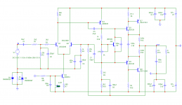
I prefer to call this personal preference, maybe because of the devices I had and used in my actual build.The attached schematic does have some slight changes notably the addition of c6(in parallel with the LED) C7(phase lead cap) C10(driver current stabilizer?) & C9(bias gen bypass cap).
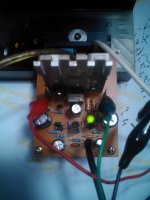
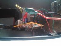
This is how it happened, while rummaging into a box of old boards I found a couple of home-etched P3A pcb. The next day I found myself populating them but this time having learned to run a simulation program I was tempted and entertained the idea of personalizing a P3A build (not meant to be completed and housed into a chassis but let us see).
The idea came from one of member Stee's posting of a CFP output schematic with attached e-lytic cap
at its drivers, also it shows on one schematic done by member ljm. I also have fragments of images of a Forsetti amp with TMC vas stage posted long time ago to one of Sakis thread (I do think member Valery run it in sim).
Going back to P3A, simulation shows
that adding a phase lead cap connected to the negative rail driver purges the appearing transient spikes at higher frequencies, but THD rises so the value is critical. I found out that the e-lytic cap mentioned at the emitter drivers seemed to be proportionate with the phase lead cap. I simulated
C10 starting at 100n - 1000uf and C7 starting at 3pf - 12pf. Pairing value that worked faster to kill the appearing transient spikes was 5.6pf and 100uf (5.6pf because I have them NPO
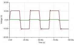
ceramic). VAS cdom is also critical, working values per simulation is between 47pf - 68pf too low and too high a value make the spikes appear and larger, at 47pf can we say that it slews much faster?. R11 and R12 driver current load was decreased to a low 56r this makes about 11ma. of current significantly larger than the original of about 2ma.(220r). I've read that feeding larger current to the drivers can make the amp more tolerant of difficult loads. I think a few medium powered CFPs had it at 47r - 100r depending on the rail voltage. 100n in parallel with the LED helps decrease THD figure. I saw others using different color but it messes the current balance the green one works best here the same with R10 (3k3 bootstrap) others uses a lower 2.7k but it only shows more current at the output and an added THD figure. I stick with the original 3k3. Adding C9 (bias gen bypass cap) seemed to be very sensitive to THD, a value like 1uf - 10uf, THD increases instantly.(could be the reason why the original circuit does not have it?). One interesting find with sim results is by increasing R6 (560r Q1 collector) to 680r it makes the tail current equally closer but DC offset triples in effect. I tried it in my actual build and I got 55mv dc offset!
With regards to sonic output, nothing noticeable according to my hearing senses (in comparison with the original), sounds very P3A to me. I think I tested it for about 4hrs (finished 2 albums) at a low 15mv idle current(measured across both output re) driving 6ohms speakers. Dead
silent and still no turn on/off thump just like the original design. I should mention that 100pf across b-c of Q6 driver is now omitted, I think Rod mentioned it as compensation
to kill the "mysteriously" appearing parasitic oscillation at the negative rail. I think member Sakis has his point that a very good pcb lay-out in P3A design can prevent this parasitic oscillation from occuring.
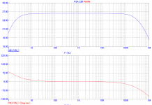
Simulation results in terms of phase,gain and THD shows only a fraction of a decimal point between the plain P3A and my work (P3A pref), and cannot be accounted as an improvement (or less degradation?). For this reason I am only displaying the significant changes made according to simulated results and that is the transient response at 30khz, this is where changes becomes evident. I am no expert so simulated
harmonic content, open loop response, IMD, spectrum analysis etc. will not be displayed. Still it has to be tested in the actual build. Again simulated results will be diffferent from the original P3A as I am not using the reccomended device model, the objective is to eliminate the 100pf across the b-c junction of the negative rail driver by keeping the input and vas stage as with the original.
Cheers!
Albert
I guess I will be adding another attempt to an endless modification of the popular. great sounding P3A design, call it modification,upgrade,tinkering etc...
I prefer to call this personal preference, maybe because of the devices I had and used in my actual build.The attached schematic does have some slight changes notably the addition of c6(in parallel with the LED) C7(phase lead cap) C10(driver current stabilizer?) & C9(bias gen bypass cap).
This is how it happened, while rummaging into a box of old boards I found a couple of home-etched P3A pcb. The next day I found myself populating them but this time having learned to run a simulation program I was tempted and entertained the idea of personalizing a P3A build (not meant to be completed and housed into a chassis but let us see).
The idea came from one of member Stee's posting of a CFP output schematic with attached e-lytic cap
at its drivers, also it shows on one schematic done by member ljm. I also have fragments of images of a Forsetti amp with TMC vas stage posted long time ago to one of Sakis thread (I do think member Valery run it in sim).
Going back to P3A, simulation shows
that adding a phase lead cap connected to the negative rail driver purges the appearing transient spikes at higher frequencies, but THD rises so the value is critical. I found out that the e-lytic cap mentioned at the emitter drivers seemed to be proportionate with the phase lead cap. I simulated
C10 starting at 100n - 1000uf and C7 starting at 3pf - 12pf. Pairing value that worked faster to kill the appearing transient spikes was 5.6pf and 100uf (5.6pf because I have them NPO
ceramic). VAS cdom is also critical, working values per simulation is between 47pf - 68pf too low and too high a value make the spikes appear and larger, at 47pf can we say that it slews much faster?. R11 and R12 driver current load was decreased to a low 56r this makes about 11ma. of current significantly larger than the original of about 2ma.(220r). I've read that feeding larger current to the drivers can make the amp more tolerant of difficult loads. I think a few medium powered CFPs had it at 47r - 100r depending on the rail voltage. 100n in parallel with the LED helps decrease THD figure. I saw others using different color but it messes the current balance the green one works best here the same with R10 (3k3 bootstrap) others uses a lower 2.7k but it only shows more current at the output and an added THD figure. I stick with the original 3k3. Adding C9 (bias gen bypass cap) seemed to be very sensitive to THD, a value like 1uf - 10uf, THD increases instantly.(could be the reason why the original circuit does not have it?). One interesting find with sim results is by increasing R6 (560r Q1 collector) to 680r it makes the tail current equally closer but DC offset triples in effect. I tried it in my actual build and I got 55mv dc offset!
With regards to sonic output, nothing noticeable according to my hearing senses (in comparison with the original), sounds very P3A to me. I think I tested it for about 4hrs (finished 2 albums) at a low 15mv idle current(measured across both output re) driving 6ohms speakers. Dead
silent and still no turn on/off thump just like the original design. I should mention that 100pf across b-c of Q6 driver is now omitted, I think Rod mentioned it as compensation
to kill the "mysteriously" appearing parasitic oscillation at the negative rail. I think member Sakis has his point that a very good pcb lay-out in P3A design can prevent this parasitic oscillation from occuring.
Simulation results in terms of phase,gain and THD shows only a fraction of a decimal point between the plain P3A and my work (P3A pref), and cannot be accounted as an improvement (or less degradation?). For this reason I am only displaying the significant changes made according to simulated results and that is the transient response at 30khz, this is where changes becomes evident. I am no expert so simulated
harmonic content, open loop response, IMD, spectrum analysis etc. will not be displayed. Still it has to be tested in the actual build. Again simulated results will be diffferent from the original P3A as I am not using the reccomended device model, the objective is to eliminate the 100pf across the b-c junction of the negative rail driver by keeping the input and vas stage as with the original.
Cheers!
Albert
Attachments
you have no method to check that your input LTP is balanced.
you have no degeneration resistors on Q1, Q2 & Q4. try 100r for Re on 1 & 2, try 10r for re on 4.
you have no base stoppers on Q5, Q6 (try 10r), Q7 & Q8 (try 1r0)
Vr1 is somewhat high. try 500r, or 1k.
Add a series resistor to Vr1 to limit the maximum bias voltage from the multiplier. try 300r.
2sb649 for Q4 is crap. Use a low Cob with as high a gain+fT as you can afford.
C1 is far too big.
C4>=sqrt(2)*{R2+R1}/R4*C1
try 150uF or 220uF for C4 and reduce C1 to 3u3F MKT, or MKP(big and expensive)
R5~=R1+R2 try 24k
Q5+Q6+Q9 should be on a common heatsink/plate.
To compensate for the reduction in open loop gain by adding the three degeneration resistors you may need to increase the Q3 CCS current. Maybe as much as double.
The low Cob for Q4 may require C5 to be increased, start with 100pF and reduce until you see excessive overshoot on a 1kHz sqwave.
Try adding a 50k VR in series with C7 5p6F and use that in combination with C5 to trim the overshoot.
I would add an L||R before you reach the speaker terminals. try 1uH||4r7 and add 4r7+100nF across the speaker terminals. That will give you a total output Zobel of ~5r+200nF, spread equally at the output devices and at the speaker terminals.
Your simulated output offset is almost certainly due to imbalance in the input LTP.
Read off the currents and voltages at BOTH ltp transistors.
Similarly changing R7 will change the ltp balance.
I found this story interesting. I'm not good at this debugging.
I simulated
C10 starting at 100n - 1000uf and C7 starting at 3pf - 12pf. Pairing value that worked faster to kill the appearing transient spikes was 5.6pf and 100uf Adding C9 (bias gen bypass cap) seemed to be very sensitive to THD, a value like 1uf - 10uf, THD increases instantly.(could be the reason why the original circuit does not have it?).
Last edited:
Hi Andrew,
The P3A schematics discussed here and reported by Abetir comes from Rod Elliott. Thousands (millions?) of DIYers all around the world have built it , including myself. I used the bjts as in the original schematics. I can guarantee that the recommended values are correct and the the amp works beautifully even if the design is very simple. It is actually playing as I type.
Cheers,
Jacques
Andrew,
I was keeping my circuit as close as possible from the plain P3A, that is why no degenerators and base stoppers added. Adding so, my circuit may no longer qualify as P3A like. VBE circuit of the plain P3A works nicely, trimmer adjust at about 50-60% I got the recommended output idle current. Q3 ccs current I think is high enough, over 3ma. but I may have to try a few of your suggestion and see what will happen..
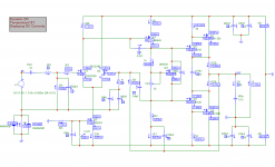
For reference, and still keeping it P3A like, the below schematic shows a really nice balance of currents and a low dc offset (3mv) except maybe by using red led for the cs and inserting 22r re for VAS.
..but the thing is in my actual build DC offset is way too high ( measured at 112mv) I find it odd...
I was keeping my circuit as close as possible from the plain P3A, that is why no degenerators and base stoppers added. Adding so, my circuit may no longer qualify as P3A like. VBE circuit of the plain P3A works nicely, trimmer adjust at about 50-60% I got the recommended output idle current. Q3 ccs current I think is high enough, over 3ma. but I may have to try a few of your suggestion and see what will happen..
For reference, and still keeping it P3A like, the below schematic shows a really nice balance of currents and a low dc offset (3mv) except maybe by using red led for the cs and inserting 22r re for VAS.
..but the thing is in my actual build DC offset is way too high ( measured at 112mv) I find it odd...
Attachments
..but the thing is in my actual build DC offset is way too high ( measured at 112mv) I find it odd...
Abetir,
Did you try matching the inputs?
Cheers,
Jacques
- Home
- Amplifiers
- Solid State
- P3A-More upgrades