DouglasSelf said:Just a thought- does any one know when the original Sanken SAP transistors were introduced?
I seem to recall it was about 15 years ago, but I could be quite wrong. Any info would be much appreciated.
By the way, one advantage of all temperature-sensing output transistors that no-one seems to have mentioned is that it saves the time required to mount a bias sensing component, which can be an awkward business. In production that might help offset their greater cost.")
Hello Doug,
I bought my first ones in 1997 I think, at that time they had several types like SAP12, SAP15, SAP16.
Jan Didden
Re: Re: do we need stable bias current with temp in the output stage? NO
I copied this post in the thermaltrak thread from B Cordell.
There are some other little developments there and a reaction from B Cordell agreeing with this
Do you believe that the spice models are accurate enough to simulate this? I asked the question to Andy_c in the spice thread but I have not yet an answer.
Jean-Pierre
janneman said:
Jean-Paul/Pierre,
VERY interesting reasoning. I must look into that better, sorry I reacted so late. Hmm. What does anybody else think about this?
Jan Didden
I copied this post in the thermaltrak thread from B Cordell.
There are some other little developments there and a reaction from B Cordell agreeing with this
Do you believe that the spice models are accurate enough to simulate this? I asked the question to Andy_c in the spice thread but I have not yet an answer.
Jean-Pierre
gaetan8888 said:Hi
I know the roender amp using Onsemi thermal track.
I did found few of those transistors, but I still hesitate to use 3 in parallel, like in the roender amp, to get the right number of diodes for the correct bias. And anyway I don't have enough Onsemi thermal track transistors to do like in the roender amp.
Anyone try it using only one transistor per side with a VBE and only one thermal track diodes per side ?
My diy amp work super and it have a Self type II output and I would like to try the thermal track transistors on my amp.
Thank
Bye
Gaetan
Hi Gaetan
It is expensive to use more NJL output devices just to get the right number of diodes, and in my opinion the application note misses the point utterly by trying to compensate driver temperatures with output temperatures. That app note really is a bit of a disgrace.
My first thought was the attached circuit, which is I think what you might be looking for.
I would be glad to have people's comments on it.
Douglas
Attachments
DouglasSelf said:
Hi Gaetan
It is expensive to use more NJL output devices just to get the right number of diodes, and in my opinion the application note misses the point utterly by trying to compensate driver temperatures with output temperatures. That app note really is a bit of a disgrace.
My first thought was the attached circuit, which is I think what you might be looking for.
I would be glad to have people's comments on it.
Douglas
Do you expect the thermal delay to be less critical for the drivers?
What do you think of the possibility to control the Vbe tempco of the diodes by bleeding of current via // resistor and adjust it to have minimum distortion at high temperature as I proposed in the other thread on thermaltracks
Thanks for your opinion
JPV
DouglasSelf said:
Hi Gaetan
It is expensive to use more NJL output devices just to get the right number of diodes, and in my opinion the application note misses the point utterly by trying to compensate driver temperatures with output temperatures. That app note really is a bit of a disgrace.
My first thought was the attached circuit, which is I think what you might be looking for.
I would be glad to have people's comments on it.
Douglas
Hi Doug,
You are so very right about the app note being wrong to lump in driver Vbe with power transistor Vbe, as if all were alike. The circuit you show looks like it should work.
One of the key things to bear in mind is the tempco matching of the ThermalTrak diode as compared with the tempco of the ThermalTrak power transistor; one has to be very intentional about the current one runs through the diode to get the desired tempco, as junction drop tempco is always a function of current density.
Another approach is to build the tracking diodes into a separate Vbe multiplier so that their net effective tempco (mv/C) can be multiplied by the amount desired while running the nominal VAS bias current through the diodes. Then a second Vbe multiplier can be used to mop up the remaining bias spread needed by the drivers et al. Lots of different possibilities here.
Cheers,
Bob
Bob Cordell said:
Hi Doug,
You are so very right about the app note being wrong to lump in driver Vbe with power transistor Vbe, as if all were alike. The circuit you show looks like it should work.
One of the key things to bear in mind is the tempco matching of the ThermalTrak diode as compared with the tempco of the ThermalTrak power transistor; one has to be very intentional about the current one runs through the diode to get the desired tempco, as junction drop tempco is always a function of current density.
Another approach is to build the tracking diodes into a separate Vbe multiplier so that their net effective tempco (mv/C) can be multiplied by the amount desired while running the nominal VAS bias current through the diodes. Then a second Vbe multiplier can be used to mop up the remaining bias spread needed by the drivers et al. Lots of different possibilities here.
Cheers,
Bob
Hi Bob
From reading the other thread I gather that you have determined that the transistor Vbe temperature coefficient is -2.14 mV/ ºC while the diode has -1.7 mV/ ºC, and the best voltage matching occurs when the diode current is a quarter of the transistor Ic. That suggests that my circuit will leave the output devices somewhat under-compensated, even if the respective currents are scaled correctly. Guessing at a quiescent Ic of 100 mA, that means 25 mA through the diodes, which suggests a VAS buffer would be required.
I think you're right- some multiplication of diode tempco is required.
Douglas
Hello
ONsemi ap notes are like their transistors spice models... not alway reliables.
Do their distortions measurements of the VBE bias and Thermal Track bias are reliables ?
And does using a Thermal Track bias in a amp really made a sonical difference compared to VBE bias ?
Thank for your ideas and advices Doug, Bob and JPV
Bye
Gaetan
An externally hosted image should be here but it was not working when we last tested it.
gaetan8888 said:Hello
ONsemi ap notes are like their transistors spice models... not alway reliables.
Do their distortions measurements of the VBE bias and Thermal Track bias are reliables ?
And does using a Thermal Track bias in a amp really made a sonical difference compared to VBE bias ?
Thank for your ideas and advices Doug, Bob and JPV
Bye
Gaetan
The THD measurements in the app note are worthless because most them appear to have been made with no load. What ONsemi are thinking of I do not know.
Douglas
DouglasSelf said:
The THD measurements in the app note are worthless because most them appear to have been made with no load. What ONsemi are thinking of I do not know.
Douglas
Hello
Oops, I've see that graph today, I should have seen that.
Did you done distortions measurements on amps using the VBE bias and Thermal Track bias to made comparaisons between them ?
Thank
Gaetan
Something similar to this could be used to multiply the temperature coefficient of the thermal traks. For a 2-stage darlington output the multiplication will be about 1.5 making the temperature coefficients about the same. For a triple darlington the multiplication will probably be too high - but this can be lowered by inserting diodes or diode connected transistors (probably 2) in series with R1. These can be used to sense driver transistor temperature.
Attachments
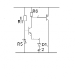
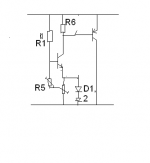
megajocke said:Or you could do this - making temperature coefficient of thermaltrak diodes adjustable. Pot turned upwards gives no multiplication, downwards multiplication increases. Bias voltage needs readjustment though when that is adjusted.
Is the simple Vbe multiplier like the Leach one not the easiest and perhaps the best because very low interraction
The potentiometer in the lower leg of the base tunes the Vbias and the diodes in the upper leg tune the drift of the drivers and of the output transistors for minimal distortion at high temperature. This is easy done by adjusting // bleeder resistors.
JPV
megajocke said:It is easy but if you have only 1 pair of outputs in a smaller amp than the Leach it might be possible the temperature coefficient of the diodes is not enough to compensate. Best would be to try it. 4 diodes like the Leach might be overcompensated.
But that is the main point. By letting the diodes working at lower current you can adjust the tempco to the tempco of the transistors.
The amount of output transistors do not matter. You take the 2 diodes of one pair is serie with the diodes of the driver pair. They will exist in a small amp or in a big amp with many ouput pairs in //
The optimal Vbias is set by the potentiometer in the base leg. Of course you will need two normal diodes in each base of each driver to bias correctely the Vbe multiplier and not overcompensate. In this configuration the Vbias is > 4 voltages drops of diodes + Vbe, depending on the multiplication factor.
JPV
Re: Re: do we need stable bias current with temp in the output stage? NO
Hi Gaetan
I had a quick look at this circuit today, and I'm not sure it will do the job. The current through the diodes is only 1.2 mA, and their voltage drop (which with this circuit is simply added to the output voltage, and not multiplied in any way) will therefore be much too low to cancel the output device Vbe's. Bob Cordell's figures show that 25 mA gives a good match for 100mA in the outputs.
Minimum output voltage is 4.13V, which seems too much; that's seven Vbe's.
Presumably the transistor in the Vbe multiplier is thermally coupled to the drivers? You mentioned something about two more diodes, so I may have that wrong.
Douglas
gaetan8888 said:
Hello
Like that ?
Thank
Gaetan
Hi Gaetan
I had a quick look at this circuit today, and I'm not sure it will do the job. The current through the diodes is only 1.2 mA, and their voltage drop (which with this circuit is simply added to the output voltage, and not multiplied in any way) will therefore be much too low to cancel the output device Vbe's. Bob Cordell's figures show that 25 mA gives a good match for 100mA in the outputs.
Minimum output voltage is 4.13V, which seems too much; that's seven Vbe's.
Presumably the transistor in the Vbe multiplier is thermally coupled to the drivers? You mentioned something about two more diodes, so I may have that wrong.
Douglas
JPV said:
Do you expect the thermal delay to be less critical for the drivers?
What do you think of the possibility to control the Vbe tempco of the diodes by bleeding of current via // resistor and adjust it to have minimum distortion at high temperature as I proposed in the other thread on thermaltracks
Thanks for your opinion
JPV
As to the first question, I think that in an EF output stage the driver dissipation varies much less with output level than it does in the output devices, (see Fig 13.1 in the 4th edition of Audio Power Amplier Design) so it should be much less of a problem.
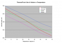
Not quite sure I understand the second question. Are you saying that the diode tempco will vary with the current through it? Apart from anything else, Bob Cordell's graph (which I take the liberty of attaching) says otherwise.
Douglas
Hi Douglas,
One manufacturer I know of used glass signal diodes between the C and E leads on the driver transistors. In this way they could track the die temperature better in the driver stage. A little heat sink grease blocked air currents from altering the temperature of the signal diodes. The Vbe multiplier transistor was mounted on the heat sink between the output devices.
From what I have seen in service, a slight overcompensation for bias control seems to work the best. Some of this is related to the heat sink size and air flow also. So an over compensated amp on my bench may well be under compensated in the customer's set up. Even the top cover position will change the bias tempco as everything else runs warmer with the top on.
I raise these points because we tend to talk about output circuitry in isolation when in fact we need to consider the entire system. In this case, all changes in the circuitry operation due to temperature rise. This can easily take a critically compensated output stage and turn it into a thermal runaway victim. I have seen this too many times over the years.
-Chris
- Status
- This old topic is closed. If you want to reopen this topic, contact a moderator using the "Report Post" button.
- Home
- Amplifiers
- Solid State
- On Semi ThermalTrak