I did not forget all the D1V3 users here and thus I offer an upgrade of the Jfet IV (attached) but I only provide the critical parts (K369BL x 8, Resistors x 8 and VR 100 ohm x 4). The cost is $13 include shipping to worldwide.
The upgrade improve the D1V3 by about few points but I would say it is a better upgrade from PCM63P-K to PCM63P-K2, KY or Y.
The upgrade improve the D1V3 by about few points but I would say it is a better upgrade from PCM63P-K to PCM63P-K2, KY or Y.
Attachments
pinial26,
I only provide PCM63PK chips at this moment.
The converter board I use is designed for PCM1702. For Pcm1704, the digital supply +ve and -ve pin must be reverse connection and thus I need to cut trace and solder two wires at the bottom. So there is no PCM1704 converter board available from me yet and I cannot offer any price.
Regards, Spencer
hello Spencer , its about half year passed  untill today i finaly started solder both dv3 dac's , and find just now that new version is available.
I forget one thing, if your new pcb have more space, I am not able to put in any more seriuos metalized 0,1uf fil cap. wima MKS will fit but smallest wima MKP will not fir in with in pcb are only 2mm and wima MKP is 3-4mm (pcb pi spacing is 5mm and OK , height not important)
I think I may order one extra kit to compare.
untill today i finaly started solder both dv3 dac's , and find just now that new version is available. I forget one thing, if your new pcb have more space, I am not able to put in any more seriuos metalized 0,1uf fil cap. wima MKS will fit but smallest wima MKP will not fir in with in pcb are only 2mm and wima MKP is 3-4mm (pcb pi spacing is 5mm and OK , height not important)
I think I may order one extra kit to compare.
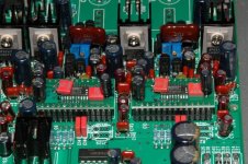
The D1V3 and D1V33 pcb are same size, same mounting hole position, same connector position and use same size parts for the 0.1uF film cap, ie 5mm pitch and size3x8mm. If you have a bigger size film cap, some of the location near the jfet IV section may not be fitted. For bigger size cap, you have to solder on the bottom!
In D1V33, I change to Panasonic 0.047u 50V ECQ-V or ECQ-B (old version but bigger size) and I find most of the locations can be fitted.
MKP is more expensive and may be better for signal coupling but I think MKS or mylar cap is ok for supply decouple.
You can PM me if you are interested in the new version. Thanks.
Squeezebox SB3 slave to D1V3 clock:
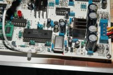
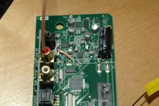
Put a 11.2896Mhz clock and other regulator parts in D1V3, R95 change to 330 ohm and then put a 220 ohm at J20 "CLK to G". This is to reduce the 5V clock peak peak level to about 3.3V for SB3 use. Connect the clock out via a SMA size coaxial cable and BNC socket as shown.
One the SB3 side, remove Y1, cut trace between HC04 pin 8 and crystal pad. Use the coaxial cable, connect the center wire to pin 9 of HC04. The ground pin connect to crystal pad which is then grounded to pcb to the nearest cap ground pin.
On D1V3, set jumper J9 to XO side. Power up D1V3 and then SB3. Play music as usual. Note that a hard reset on SB3 is required if the SB3 input clock is off before.
Note that I do not see much improvement on the digital out of SB3 by using linear power supply or adding a pulse transformer at the digital output.
Enjoy!
Attachments
Here is the AP FFT measurement on the digital out of SB3 when playing back 1kHz and 18kHz files. Note that it is the FFT without the D1V3 DAC part.
My AP FFT cannot tell any difference between original SB3 or clock/regulator modifications. Guess it is due to the very low jitter level of the signal at the SPDIF digital out of SB3.
The improved sonic on D1V3 is observed due to the use of low jitter supper clock at the XTI of SM5842 digital filter chip.
Attachments
I have created my blog here:
http://www.fetaudio.com/
You can save your time to go through the whole thread if you are interested in D1V3 or D1V33 information. Thanks for visiting.
http://www.fetaudio.com/
You can save your time to go through the whole thread if you are interested in D1V3 or D1V33 information. Thanks for visiting.
Hi Spencer,
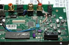
I have bought (second hand) the kit (D1V33 with PCM63) from another french guy who did not start to solder anything yet. I am wondering if you plan to sell the PCM63->PCM1704 adapter card that is to be seen on your blog ?
If not, do you think that other adapters (like monarchyaudio, etc ...) may work ?
Anyway I am not in a hurry, I have not started to mount the components yet ...
Thanks
Akira
Akira,
The adaptor pcb I am using is for PCM1702 design. Also the pad width is a bit wide and thus I need to straighten the leads of the IC before I can solder the chip on the pcb! Moreover PCM1704 has two supplier pins reversed compare to PCM1702. The board I do thus need to cut trace and jump two wires on every converter and is mainly for my testing only and not able to offer for sales.
I think if any converter board is compatible for PCM63 pin assignment, then it should work as it is not really difficult to do the pcb.
Anyway you can ask again when you have you PCM63 running on the kit.
- Home
- Vendor's Bazaar
- NP D1 DAC clone with enhancement