Hi CNX,
I tried to download the pdf data sheet for your soft start module v2 but my PC tells me the file is corrupt. I have tried several times. I was wondering if you could send me the data sheet pdf? My email is richie_reginald at yahoo.co.uk - Time to assemble my 3020 very soon!
Cheers,
Richard.
I tried to download the pdf data sheet for your soft start module v2 but my PC tells me the file is corrupt. I have tried several times. I was wondering if you could send me the data sheet pdf? My email is richie_reginald at yahoo.co.uk - Time to assemble my 3020 very soon!
Cheers,
Richard.
for those which cannot access the manual for Power softstart from the product page, please try the following link:
http://www.connexelectronic.com/documents/Power_SoftStart.pdf
http://www.connexelectronic.com/documents/Power_SoftStart.pdf
cnx said:reply sent, pls check mail.
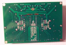
Hello Cristi, I got your reply. I enclose a picture of your board where I draw the two points that should be bridged in order to use the screw connectors once the rectifier bridge has been removed. The two arrows, are not that nice, but you can see the two briged points quite clearly I have drawn them in red.
Also, the + should be on the left side, and - is on the right. Am I right?
The PSU I built uses a center tapped transformer, and I will not remove the big capacitors as per your advice.
Please, just confirm that the drawings in the picture are correct.
Thanks!
Attachments
pincellone said:
Hello Cristi, I got your reply. I enclose a picture of your board where I draw the two points that should be bridged in order to use the screw connectors once the rectifier bridge has been removed. The two arrows, are not that nice, but you can see the two briged points quite clearly I have drawn them in red.
Also, the + should be on the left side, and - is on the right. Am I right?
The PSU I built uses a center tapped transformer, and I will not remove the big capacitors as per your advice.
Please, just confirm that the drawings in the picture are correct.
Thanks!
just bridge the connection as in the photo, and measure the coresponding pins on the screw connector to connect them correctly.
lorylaci said:Hi!
I've got a huge transformer with 2x60V AC secs.
Do you got any class D modules, that can be used with this?
I would like to drive my 18" woofers...")
with 2x60V AC you will get about +-84V. this is suitable for TA0105A amplifier. http://connexelectronic.com/product...ucts_id/109?osCsid=44s0prbb405s2nm6n3j9g8noo6 with this voltage you will get aout 500-600 W on 4 Ohms load.
lorylaci said:Can I use my transformer with the IRAudAmp7 module too?
I always wanted to build that. My prototype never worked
the voltage after rectifier and filter caps will be about +-83V which is a little too high for IRaudamp7. i recommend to not use that high voltage, altough with 250V rated MOS-FET's can work at this voltage. better try the TA0105A amp. this will work fine even at higher voltages.
OK, I will order a TA0105 I'm sure.
My transformer has an other 12V winding, so I will use that to make the satblized V5 supply. And I will stabilize the VN12 from the main supply. Or does the board has on board stabilizers?
I see from the datasheet that the IC draws 190mA from the VN12, this would mean 10-20W dissipation if I stabilize it from the main supply.
cnx said:the 2 pcs 2.2uF yellow caps are the input caps, they are needed for proper operation of the amplifier. do not try to use the amplifier without them, because in the best case will not work. a DC offset of few mV will shut-down the amp.
Cnx, I was not talking about the yellow caps that are soldered onboard.
The TA3020 V. 2 amp came also with two brown polyester caps in a small plastic bag, what are they for? I was wondering if they should be soldered in series with the rca input connectors. There are others soldered onboard, same type.
Thanks
pincellone said:
Cnx, I was not talking about the yellow caps that are soldered onboard.
The TA3020 V. 2 amp came also with two brown polyester caps in a small plastic bag, what are they for? I was wondering if they should be soldered in series with the rca input connectors. There are others soldered onboard, same type.
Thanks
i was checking thru all our messages, but i can't find what for i sent you those caps. anyway, there are few months since then, i think you ask me to send you for the power supply, if they are 0.1uF or 0.22uF. also could be to lower the output filter cutt-off frequency, if you mount in parallel with existing caps or replace them. if you remember, pls send me mail and i will tell you how to use them.
- Status
- Not open for further replies.
- Home
- Vendor's Bazaar
- NEW Audio amplifier kits, modules and many others.