The silkscreen also shows which way the notch in the socket has to face when the socket is inserted.
Wow, I totally missed that. So, I don't have to unsoldering the ones that are backward as long as I get the chip in correctly, I'll be ok. Later, the risk would be replacing the IC and getting it in backwards based on the wrong orientation of the notch. I hope the memory doesn't fade too fast or I could be in trouble. Maybe I'll put a label in the case of the incorrect ones to warn future techs. I don't want to remove and replace those sockets as it sounds too risky. That was the hardest soldering for me, as a noob, to do.
Thanks all,
rick
MyRef Ultimate Rev C Updated BOM and Tutorial
I've updated both the BOM and the Tutorial.
Tutorial:
Some minor corrections to text and layout
BOM:
Removed most of the alternate parts.
Added for Europeans RS Components P/Ns for Digikey parts so that a Mouser overseas order and two domestic orders (RS and Banzai Music) are all.
Adjusted colors and layout.
Revised all notes
I consider this the first final release (1.0) of both documents.
Now only some 'Audio grade' resistors and some elcos could possibly change and will be reported in the other thread.
Attachments
Last edited:
I consider this the first final release (1.0) of both documents.
Never say never...

I've added to the BOM Distrelec codes for European Builders.
Attachments
I've had a quick read through Dario's build guide -thanks Dario - just to check if I'd made any major blunders on the couple of boards that I've already populated.
Everything seems ok apart from the zener diodes that I've mounted flush with the board but the guide advises mounting them raised. Is this essential? I haven't had a chance to connect the boards up yet, but I have trimmed all of the component legs.
Should I order new diodes and replace them before connecting up?
Thanks.
Hi Which type of transformer is better for this amp R-core or Toroidal or does it not matter thanks john
Both are good.
In my setup a Selectronic R-Core is better than a Toroid toroidal.
My R-Cores sounds a bit fuller, my toroidal is a bit more dry and impulsive.
Everything seems ok apart from the zener diodes that I've mounted flush with the board but the guide advises mounting them raised. Is this essential?
...
Should I order new diodes and replace them before connecting up?
It's better but it's not essential.
Just keep monitored their temperature, if they're not hot they should be safe.
Last edited:
I've had a quick read through Dario's build guide -thanks Dario - just to check if I'd made any major blunders on the couple of boards that I've already populated.
Everything seems ok apart from the zener diodes that I've mounted flush with the board but the guide advises mounting them raised. Is this essential? I haven't had a chance to connect the boards up yet, but I have trimmed all of the component legs.
Should I order new diodes and replace them before connecting up?
Thanks.
All 4 of my channels were mounted flush and worked for extended periods (days on continuously) but I can't comment on the long term impact as they are in storage at the moment.
I "think" they will be fine but if they do smoke they are a cheap easy repair.
My kit has been coming together slowly but now it is almost ready to test. The one outstanding issue is that one of my chips isn't flush to the heatsink.
To mount I drilled then tapped the heatsink (no problems), used thermal paste along with the washer and insulation, and screwed the chip into place. One channel was great and the chip was flush but on the other chanel there is a slight gap between the chip and the sink on the lower left hand side. The board seems to be right up against the sink so there is not a lot of room to move things. Has anyone else had similar troubles? Is there a quick fix?
The three options I am consdering are: 1) desolder the chip and try to fit it better, 2) bend the leads on the chip, 3) find some aluminum spacer to insert between the chip and sink.
Any help or advice is appriciated. Thanks!
Hey fluffy! I think I would desolder the front legs of the chip while prying them a bit with a tiny flat head screwdriver. So when the solder flows the leg comes up a bit. Then wait for chip to cool a little and do it again. The back row are probably fine. You just soldered them in to deep in the front so the chip leans forward rather than sitting up straight. If you can push it backward a little without to much stress on the legs then try that first.
Uriah
Uriah
I've had the same problem just this evening. I am about to finish the enclosure for my amp and both of the don't seem to properly fit. I am done with thermal paste. Heat transfer surface will not be the most optimal, but I've been running it without thermal paste for more than 1 month, and it barely got warmMy kit has been coming together slowly but now it is almost ready to test. The one outstanding issue is that one of my chips isn't flush to the heatsink.
To mount I drilled then tapped the heatsink (no problems), used thermal paste along with the washer and insulation, and screwed the chip into place. One channel was great and the chip was flush but on the other chanel there is a slight gap between the chip and the sink on the lower left hand side. The board seems to be right up against the sink so there is not a lot of room to move things. Has anyone else had similar troubles? Is there a quick fix?
The three options I am consdering are: 1) desolder the chip and try to fit it better, 2) bend the leads on the chip, 3) find some aluminum spacer to insert between the chip and sink.
Any help or advice is appriciated. Thanks!
It has been documented that the chip placement was not optimum in relationship with the edge of the PCB and a "large" heatsink that continued below it.
My solution was to solder in just enough to of the LM3886 legs to extend through the PCB which gave me longer "top side" legs to bend to the heat sink.
That obviously isn't an option if the LM3886 is already soldered in place.
"MY" first choice would be re-solder the leads if they weren't trimmed, but my solder experience may differ.
"MY" second choice would be an Aluminum spacer between chip and HS.
Good luck with "YOUR" choice, and worst case is relatively minor and consists of completely removing and replacing the two LM3886 chips if they are damaged...
What I did was to insert chip into pcb and stand pcb upright whilst pressing down on chip against work surface, then move pcb to exact upright position - using set square and clamp if you like - solder a couple of pins to hold in place before soldering remainder.
The result is you get a perfect 90 degree angle in line with edge of pcb.
The result is you get a perfect 90 degree angle in line with edge of pcb.
Trim the PCB
there are only 3 components that prevent significant trimming of the PCB. R8, R9 & R10.
R8 & R9 are on a common pad that has lots of space to move the pin holes inboard.
R10 is soldered to a big pad on the top side. Again the pin hole can be drilled inboard.
Drill three 0.7mm holes in line with the existing holes but moved inboard by 1.5mm.
Trim off 1mm of PCB across the whole width. Grind/file/saw.
Scrape away some of the mask around each new hole.
Stand these three resistors on end at the holes labeled R8, R9, R10. Bend the top lead over in a big radius. If you think it necessary slip over an insulation sleeve to prevent shorting to swarf/tools/heatsink. The three red uniformed soldiers standing to attention look just the part.
Hi,Thanks for the help guys, I'll probably try to bend the leads for an easy fix and pull out my iron to try Uriah's suggestion if that doesn't work.
there are only 3 components that prevent significant trimming of the PCB. R8, R9 & R10.
R8 & R9 are on a common pad that has lots of space to move the pin holes inboard.
R10 is soldered to a big pad on the top side. Again the pin hole can be drilled inboard.
Drill three 0.7mm holes in line with the existing holes but moved inboard by 1.5mm.
Trim off 1mm of PCB across the whole width. Grind/file/saw.
Scrape away some of the mask around each new hole.
Stand these three resistors on end at the holes labeled R8, R9, R10. Bend the top lead over in a big radius. If you think it necessary slip over an insulation sleeve to prevent shorting to swarf/tools/heatsink. The three red uniformed soldiers standing to attention look just the part.
You could place some of those isolators like the mica ones, but made of grey plastic, they are less thin than them.Thanks for the help guys, I'll probably try to bend the leads for an easy fix and pull out my iron to try Uriah's suggestion if that doesn't work.
I can't imagine worse advice than suggesting that a newbie, or even an experienced builder, start drilling, grinding, and butchering a perfectly good PCB, especially a two-sided board with closely mounted components.
Can you tilt the board or the heatsink slightly so they align better? If you're using standoffs under the board, simply shorten one or more until you get the proper angle of tilt. Must your chip be bolted to a tapped hole in the heatsink, or can you drill an oversize through hole and get a little leeway for movement? It sounds like you're very close to getting proper alignment. Just a small amount of tilting the board would probably get you there. I don't like to depend on it, but I believe there is a VERY small amount of play in the 3886 leads even after it's soldered to the board.
There are too many simple solutions to this simple problem. The very last thing I would recommend is to start grinding the board, unless it is a very small amount in an area where no components are mounted. Moving pads is a bad course of action, likely to end in disaster.
Peace,
Tom E
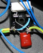
ESP Ground Breaker
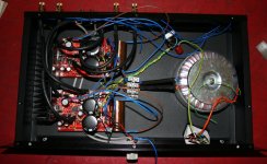
Sorry for the newbie question but does this picture of the ESP ground breaker look correct or do you disregard the AC +- markings on the bridge as it's not being socketed. Amp is sounding great. I replaced heatsink for larger one as LM3886 was getting to 72 deg celsius. Regarding LM placement and heat sink. I ground a 4mm slot in the heat sink from below stand-offs which the board slots into. Just make sure resistor leads don’t touch heat sink.
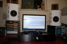
Amp is in 2U rack for use with digital Audio Workstation. Toroid is dual 22v. Volume is ebay 10k 21 step attenuator and seems plenty loud through CSS FR125s 86db & Foster leaf super tweeters.
Thanks to Uriah, Dario for help with transformer and of coarse Mauro.
Sorry for the newbie question but does this picture of the ESP ground breaker look correct or do you disregard the AC +- markings on the bridge as it's not being socketed. Amp is sounding great. I replaced heatsink for larger one as LM3886 was getting to 72 deg celsius. Regarding LM placement and heat sink. I ground a 4mm slot in the heat sink from below stand-offs which the board slots into. Just make sure resistor leads don’t touch heat sink.
Amp is in 2U rack for use with digital Audio Workstation. Toroid is dual 22v. Volume is ebay 10k 21 step attenuator and seems plenty loud through CSS FR125s 86db & Foster leaf super tweeters.
Thanks to Uriah, Dario for help with transformer and of coarse Mauro.
Attachments
Last edited:
The Disconnecting Network looks good.
The DC to DC is shorted. OK
The AC to AC is shorted. OK.
The Grn/Y comes in on one side and goes out on the other. OK.
The cap across the diodes carries extremely HF to chassis. OK.
The resistor across the diodes carries tiny current to chassis. OK.
The resistor is too big. 5W is not needed, 125mW to 600mW is sufficient. It carries leakage current from transformer to PE. These can be uA to mA.
Pic2.
I cannot see the permanent Chassis to PE connection!
I cannot see the Disconnecting Network to Chassis connection!
Last edited:
Thanks for reply Andrew. Yes, I still need to finish Chassis ground and tidy up other wiring as you mentioned. I wanted to make sure ESP ground breaker was correct first. Most of the blue wiring is from in/out wire shielding. Is this pointless? It seems very quiet.
Last edited:
- Status
- This old topic is closed. If you want to reopen this topic, contact a moderator using the "Report Post" button.
- Home
- Amplifiers
- Chip Amps
- MyRefC build guide