Finally a chassis!!
Link to More Pics of Chassis
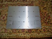
Finally I got what I needed. Remember that Chassis I was talking about a while back? Well, it is a really nice chassis but I wanted it to be perfect for the MyREFC so I got a bottom plate made for it. It perfectly matches the MyREFC boards and the 160VA toroids I have been selling. You can also fit easily a 250VA in the center and if you offset the 300VA about a quarter of an inch it will fit as well. This thing is ready to go. If you guys want them I am asking 165 each plus shipping. I think its safe to say this should remain US or Canada. Elsewhere would be silly for shipping costs, but if you must have one I will try to ship to other countries, just assume shipping will probably be 50+ to countries outside the US.
I only have 10 of these. One for me, one for Sonidos, leaves 8 of them and another half of those have been requested but I need to check and see if those folks are still interested. So 4-8 available.
Dimensions are 14" wide, 12" deep, 3.5" tall.
All screw holes in plate perfectly match the chassis. No drilling needed at all.
I think it will fit a large fllat rate USPS BOX!
Uriah
Link to More Pics of Chassis
Finally I got what I needed. Remember that Chassis I was talking about a while back? Well, it is a really nice chassis but I wanted it to be perfect for the MyREFC so I got a bottom plate made for it. It perfectly matches the MyREFC boards and the 160VA toroids I have been selling. You can also fit easily a 250VA in the center and if you offset the 300VA about a quarter of an inch it will fit as well. This thing is ready to go. If you guys want them I am asking 165 each plus shipping. I think its safe to say this should remain US or Canada. Elsewhere would be silly for shipping costs, but if you must have one I will try to ship to other countries, just assume shipping will probably be 50+ to countries outside the US.
I only have 10 of these. One for me, one for Sonidos, leaves 8 of them and another half of those have been requested but I need to check and see if those folks are still interested. So 4-8 available.
Dimensions are 14" wide, 12" deep, 3.5" tall.
All screw holes in plate perfectly match the chassis. No drilling needed at all.
I think it will fit a large fllat rate USPS BOX!
Uriah
Attachments
Last edited:
Troy,
No. This chassis is repurposed for the MyREFC. It originally would have held two ICE amp power modules from B&O. I got a hold of 10 of them for MyREFCs but the base plate of the thing has two holes in it where the modules would have fit. So I had the designer make me a baseplate that would fit over those holes and also fit our boards and toroids. The plate sits up off of the bottom by however high you want it to with standoffs. So directly beneath the chip there is a 1/8" gap if you are shooting for UL standards. So there is a lot of airflow possible as the entire thing sits off of the floor by 1/8" and the air seeps in around the entire gap. Then, those slots you see? A little L bracket is used to hold the heatsink in place. So you bolt the L bracket to the sinks, then bolt the L bracket to the baseplate and you can now slide the sink back and forth for a perfect meeting with the chip. Then tighten the bolts down and bolt the chip to the sink. Pretty nifty")
Uriah
No. This chassis is repurposed for the MyREFC. It originally would have held two ICE amp power modules from B&O. I got a hold of 10 of them for MyREFCs but the base plate of the thing has two holes in it where the modules would have fit. So I had the designer make me a baseplate that would fit over those holes and also fit our boards and toroids. The plate sits up off of the bottom by however high you want it to with standoffs. So directly beneath the chip there is a 1/8" gap if you are shooting for UL standards. So there is a lot of airflow possible as the entire thing sits off of the floor by 1/8" and the air seeps in around the entire gap. Then, those slots you see? A little L bracket is used to hold the heatsink in place. So you bolt the L bracket to the sinks, then bolt the L bracket to the baseplate and you can now slide the sink back and forth for a perfect meeting with the chip. Then tighten the bolts down and bolt the chip to the sink. Pretty nifty
Uriah
31times is ~+30dB.
Most power amps have a gain between +26dB and +32dB.
I can't see the standard gain being your problem.
Check your assembled gain.
I had just measured using a constant test tone with my DMM. 0.1vac input to the amp gave a 3.2vac across a 8ohm dummy. At this vol, my speakers is way too loud for normal listening. So it looks like my amp is indeed giving abt 32 times. Guess my speakers and room combinationinteraction could be a bit extraordinarily loud... Everything else seems fine!
3.2Vac into 8r0 is ~1.3W or +1.1dB ref. 1W0.1vac input to the amp gave a 3.2vac across a 8ohm dummy. At this vol, my speakers is way too loud for normal listening.
If your speakers are 90dB/W @ 1m then a single with 1W will be 90dB @ 1m.
A pair, each fed with 1.3W and listened to at 2.5m distance will be about 86dB @ 2.5m
That is LOUD.
I can understand why you need to attenuate the 100mVac signal to listen comfortably.
70dB@2.5m is nearly equivalent to a conversation (maybe slightly raised voices).
80dB of average level is getting loud.
90dB of average level is extremely loud.
If your CDP is putting out a maximum of 2.2Vac, can you imagine the SPL that the speakers are trying to reproduce?
Expect to attenuate a CDP by between -10dB for an extremely loud party and by -50dB for background listening that you can just about talk over.
3.2Vac into 8r0 is ~1.3W or +1.1dB ref. 1W
If your speakers are 90dB/W @ 1m then a single with 1W will be 90dB @ 1m.
A pair, each fed with 1.3W and listened to at 2.5m distance will be about 86dB @ 2.5m
That is LOUD.
I can understand why you need to attenuate the 100mVac signal to listen comfortably.
70dB@2.5m is nearly equivalent to a conversation (maybe slightly raised voices).
80dB of average level is getting loud.
90dB of average level is extremely loud.
If your CDP is putting out a maximum of 2.2Vac, can you imagine the SPL that the speakers are trying to reproduce?
Expect to attenuate a CDP by between -10dB for an extremely loud party and by -50dB for background listening that you can just about talk over.
My speakers are 95dB/W though
OK, I understand what you're saying. So everything is normal and I should not do anything to the gain and just attenuate the signal? I am using a buffer peramp, I can't imagine some other preamp with gain...
3.2Vac into 8r0 is ~1.3W or +1.1dB ref. 1W
If your speakers are 90dB/W @ 1m then a single with 1W will be 90dB @ 1m.
A pair, each fed with 1.3W and listened to at 2.5m distance will be about 86dB @ 2.5m
That is LOUD.
I can understand why you need to attenuate the 100mVac signal to listen comfortably.
70dB@2.5m is nearly equivalent to a conversation (maybe slightly raised voices).
80dB of average level is getting loud.
90dB of average level is extremely loud.
If your CDP is putting out a maximum of 2.2Vac, can you imagine the SPL that the speakers are trying to reproduce?
Expect to attenuate a CDP by between -10dB for an extremely loud party and by -50dB for background listening that you can just about talk over.
Very good and thorough explanation.

Fuse rating and power cable
I mentioned a while ago that I am putting together a six channel amp - which is coming together slowly, but I need some clarification on fuse/switch contact ratings and power connectors.
Firstly, I want to have a nice push button power switch but most of the ones I like seem to have a low current rating, so if i've got three of these transformers and six My_ref's in one case then what's the minimum fuse and switch contact rating that you would suggest using?
Secondly, I've made some power cables in the past using Chris VenHaus AC Bulk Power cable - the shielded twisted pair in the Flavor#1 configuration - and I have some cable left over. I was thinking of running this directly from the 13 Amp plug into the back of the switch in the amp - via the above fuse - but with no iec connector. So, apart from the convenience factor, is there any reason why I shouldn't do this?
Thanks
Gary
Use a Trated fuse for each transformer.
Use a Trated fuse for the mains input.
I recommend a soft start for your transformers, even if they are low VA. This allows lower value fuses to be used.
Use the switch to trigger a mains rated relay.
Or
Look up the recent thread discussing a push button switch on facility with soft start delay. This could use a 12V rated switch since it is not connected to the mains. But it does need an extra transformer to supply safe power to the switch control circuit.
I will assume you are meaning a Rated fuse.Use a Trated fuse for each transformer.
Use a Trated fuse for the mains input.
If not, what is a Trated fuse?
Must all six channels be switched on simultaneously? Must all six channels be powered through one cord? It might be more convenient to have two or even three switches, and at least two cords.
A dedicated power cord(s) is not a bad idea at all. Make sure to use adequate strain relief and protection of the insulation where the cord enters the case. Of course, you give up the chance to ever experiment with cords in the future without taking everything apart. Perhaps one IEC and one fixed? Pick the best sounding for the main channels.
The Flavor One is a good design. I use it without any shielding. Use a high quality wall plug, such as Wattgate or better, to realize its full potential. The wire is not so critical, but don't skimp on the gauge, with 12 as a minimum.
Peace,
Tom E
Andrew,
I'd like to keep the electrical side of things as simple as posssible as this is my first build, so I'll probably not bother with soft start or mains relays.
If the transformers are 300VA 2x25V then I think the input current is going to be 1.25A @ 240V. Is this right? If so, can I use a 1.25A T rated (anti surge?) fuse per transformer and a 4A T rated fuse for the mains input? Or will I need to go a bit higher without soft start? Thanks.
Tom,
I hadn't thought about switching on channels independently, it's a nice idea as most of the time I'll be listening in stereo so it makes sense.
I think I'm going to go with one good quality fused iec inlet and try some different power cords. Thanks.
Gary
Hi Stan,
for Motors and Transformers it is normal to specify the fuse rating @ 3 * Watts / Mains voltage.
For 200VA 240Vac this would be 3.1A.
A T rated fuse (same as antisurge = time delay fuse) should allow one 300VA to start up reliably without nuisance blowing every few months.
If you don't fit soft start then use 3 T3.1A, one to each transformer and T8A at the amplifier input.
The fuse rating in the plugtop will need to be either 10A or 13A.
Thanks Andrew, just what I needed to know.
I've located a latching push button switch here, it's got 12A @240V rated contacts so if I want to switch the whole lot on in one go then it should do the trick.
Will I need to fit anything across the contacts to stop arcing?
Thanks
Gary
I've located a latching push button switch here, it's got 12A @240V rated contacts so if I want to switch the whole lot on in one go then it should do the trick.
Will I need to fit anything across the contacts to stop arcing?
Thanks
Gary
Thet use to carry an A and a T, but I don't know what do they mean. I know F is for Fast-blow.So, would a "T rated" fuse be a 'slow blow'???
T2A = time delay 2Ampere
F3.1A = fast 3.1Ampere
Look up the manufacturer's data tables to find the Time vs Current. You will find that a fuse will pass it's nominal current for a long time and pass 10times it's nominal current for quite a long time in terms of semiconductor destruction times.
Most fuses also have a voltage rating, commonly 250Vac.
This is the maximum voltage it can break and guarantee to extinguish the arc after rupture.
Last edited:
- Status
- This old topic is closed. If you want to reopen this topic, contact a moderator using the "Report Post" button.
- Home
- Amplifiers
- Chip Amps
- MyRefC build guide