ident cog ceramic c10
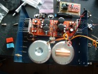
Hi Started on my amp at last .I found it hard to ident the 3 little ceramic caps at c10,12,34,so i changed c12 to a wima as recommended by Dario also c34 with a mica ,However need to ident c10 cog cap that came with the kit can someone please advise thanks john
Hi Started on my amp at last .I found it hard to ident the 3 little ceramic caps at c10,12,34,so i changed c12 to a wima as recommended by Dario also c34 with a mica ,However need to ident c10 cog cap that came with the kit can someone please advise thanks john
these three ceramic caps are all 0.1inch pin pitch.I found it hard to ident the 3 little ceramic caps at c10,12,34,so i changed c12 to a wima as recommended by Dario also c34 with a mica ,However need to ident c10 cog cap that came with the kit can someone please advise thanks john
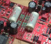
The Wima 220pF plastic film cap is 0.2inch pin pitch and fits the PCB without modification.
The two remaining ceramics need the legs bent very slightly to reach the 0.2inch pad spacing on the PCB.
the 10pF, C34 is marked 100,
22pF, C10 is marked 220,
220pF, C12 is marked 221 (this is the long lead cap),
Hi,
start with a small volume film cap and get the amp working and measured, particularly for hum & noise.
Then try substituting the big cap to see if performance deteriorates.
The size of the big cap and the spacing of it's leads will make it susceptible to picking up hum fields. This could be minor and acceptable. A before and after test is necessary.
That's a nice looking build. Sorry you're having problems at this late stage.
You can try to fit a smaller cap on the board, as Andrew suggested. A decent WIMA would probably fit there, except the Blackgate is in the way. You could try a cap smaller than the gigantic Obbligato, with leads long enough to reach the board, such as SoniCap Gen I, which I like a lot. Insulate the leads with teflon tape or tubing. I would not make the caps outboard, as Uriah suggested--too many things could go wrong in the future. It looks like there is some room in the corner next to the heatsink to stand a cap on end, but you would need to support it with some kind of mounting device. I would avoid mounting near the xformer.
You could be very brave and eliminate the cap completely, using a wire jumper instead. This allows passage into the amp of any DC present in the signal, and could be catastrophic.
Peace,
Tom E
Hi I have made a mistake and not left room for the Obbligato in my case .Would there be any problems fitting them on top of transfo s or i could just fit a smaller cap like a wima onto pcbs cheers john
Hy Lucylu,
this case is too tiny and a challenge fit...
And you need space for the LSA too...
A bigger case is an option?
You can try to fit a smaller cap on the board, as Andrew suggested. A decent WIMA would probably fit there, except the Blackgate is in the way.
...
I would avoid mounting near the xformer.
You could be very brave and eliminate the cap completely, using a wire jumper instead. This allows passage into the amp of any DC present in the signal, and could be catastrophic.
As Tom pointed out a smaller cap could be an option but avoid a Wima, a 1uF white MCAP mounts onboard and is much better.
Also avoid mounting near the transformer not only caps but also signal wires...
I wouldn't DC couple, DC coupling is good for testing components but the MyRef sound much better with (good) coupling caps in place, particularly in the bottom end.
Attachments
What gauge wire is appropriate for the input and output of this amp? I am finalizing my build and cobbling together a light bulb/variac setup. I don't want to start a wire war but: Solid core vs. braided. Teflon vs PVC. At first blush I would use solid core, teflon insulated wire. Anyone have a good source for such items?
TIA,
rick
TIA,
rick
For input signal wire almost any gauge will work, the current is so minimal that I bet that even a 30 AWG or 32 AWG gauge will work very good. Some people report that they even sound better than thicker ones.
For output wire the thicker the better (less resistance, etc...) and use copper (or silver for who believes in it), never use steel or magnetic materials.
For output wire the thicker the better (less resistance, etc...) and use copper (or silver for who believes in it), never use steel or magnetic materials.
I believe solid core (copper) will be good, I've got 14awg teflon from partsconnexion.com to make triple braided power cable for MyRefC
another one is less expensive 1,2mm solid core teflon from diyhifisupply.com - (I remember ClaveFremen used it for internal power wiring)
What about the idea to use old video tape wrapped up around the power cable to eliminate some noise? may it works similar to ferrite rings ?
another one is less expensive 1,2mm solid core teflon from diyhifisupply.com - (I remember ClaveFremen used it for internal power wiring)
never use steel or magnetic materials.
What about the idea to use old video tape wrapped up around the power cable to eliminate some noise? may it works similar to ferrite rings ?
Last edited:

I believe solid core (copper) will be good, I've got 14awg teflon from partsconnexion.com to make triple braided power cable for MyRefC
another one is less expensive 1,2mm solid core teflon from diyhifisupply.com - (I remember ClaveFremen used it for internal power wiring)
The DIYHiFiSupply cable OCC Teflon served cable is quite good, I've had also very good results with this OCC silver nude cable from eBay (Albert's Audio Store), particularly mixed with copper (copper on signal and OCC silver on signal ground).
Use AWG24/AWG22 cables for signal and AWG18/AWG16 for power output.
For signal cables, if you can find any, the Acrolink Stressfree 6N copper is incredibly good.
I'm still experimenting but what I'm using now is an Acrolink Stressfree (0.6mm)/OCC silver (0.8mm) for signal and the DIYHiFiSupply OCC Copper (1.2mm) for output.
Yes, regi. the tape from old videocassettes. I think that due to it's ferrite nature it can work similar to ferrite rings when wrapped around the cable, creating some resistance to HF noise. My idea is to wrap each individual teflon-coated wire in order to eliminate also some influence of a magnetic field of the neighboured conductors.video tape? are you referring to videocassettes?
It's only my hypothetical idea, and I'm interested if anyone has some similar experience or thoughts. and of course concerning the power cable for RevC
Vladimir
Troubleshooting
Hey guys,
I have a problem in one channel. The relay does not close when the amp is
powered up. When I turn it off, it clicks twice and the led glows between the
two clicks.
I tried reading the relay operation document, but couldn't decipher anything.
Any thoughts on what's going on? I think either Q1, Q2 or Q3 is bad.
Thanks for your help!
Hey guys,
I have a problem in one channel. The relay does not close when the amp is
powered up. When I turn it off, it clicks twice and the led glows between the
two clicks.
I tried reading the relay operation document, but couldn't decipher anything.
Any thoughts on what's going on? I think either Q1, Q2 or Q3 is bad.
Measure the output offset between the Speaker output and PGND, with the speaker disconnected. If it's below about 100mV, then the audio section (LM318/LM3886) is probably ok, and you can continue by debugging the protection section.
Check the identity of Q1 (BC639), Q2 and Q3 (2 x BC546). Check the polarity of all caps (3) and rectifiers (3) in the protection circuit. Check the values of all resistors in the protection circuit.
If all these seem ok, you can consider changing R14 to 180 ohms and R21 to 100k - IMHO, this works better to reliably turn on the relay, than the stock values of 470 ohms/220k.
Thanks man!
hmmm... never bothered to check the output offset because the relay wasn't working.
But its almost equal to the positive rail voltage. I'm measuring between the output pin and the PGND.
Checked the pins of the 3886, they are receiving the full rail voltage on both sides. The output of the chip still has the full voltage though.
Last edited:
Checked the pins of the 3886, they are receiving the full rail voltage on both sides. The output of the chip still has the full voltage though.
OK, the good news is that your protection relay circuit is probably working perfectly. You can proceed to debug the audio section.
If it's the metal-tab LM3886T version, check that the tab is isolated from the heatsink and/or the heatsink is not connected to ground. The tab is at V-, so if it shorted to ground, it most probably fried the LM3886T permanently.
Check all the usual stuff - shorts, solder bridges, polarity of all electrolytics, diodes, etc. Check the LM318 power - +/- 12V. Check the polarity of the zeners. Check the polarity of C6, C11.
Check the orientation and pin/socket contact of the LM318. Remove and reseat the LM318 if there's any doubt.
If all these seem ok, you may have a blown LM3886 and/or LM318. Replace the LM318 first and test, before attempting to replace the LM3886.
Last edited:
- Status
- This old topic is closed. If you want to reopen this topic, contact a moderator using the "Report Post" button.
- Home
- Amplifiers
- Chip Amps
- MyRefC build guide