Hi Tom,
sure it is, a lot of people use with success those 2x22V transformers but some have better regulation than others and this could be a problem...
It's for such reason that I asked to measure that voltage so that we can compare a working one with a faulty one and understand if regulation is a concern.
I agree that mounting the uninsulated version, with the due care, is pretty easy but all things that could go wrong with it simply doesn't exists with the insulated one.
In fact all my builds were done with the insulated version, simply easier and safer.")
Transformer regulation should not be an issue since the amplifier should be at idle with no input signal when the relay is supposed to close. There may be a significant difference in the AC mains voltage at various locations and that may have an effect.
The insulated LM3886 has twice the thermal resistance from chip to case compared with the uninsulated device. If mounted with care using a good insulator, the uninsulated device will have a lower thermal resistance to the heatsink. The chip will then run a bit cooler.
Hello Ben,
try to measure voltage between these two points:
Mine (2x24V sec.) measure 27V
It would be nice if someone with a working MyRef with 2x22V transformer measure also that voltage.
I suspect that your transformer, under load, regulate not so well to a voltage unsuitable for the protection circuit.
Original specs were 2x24-25V but later people found that 2x22V was better suited for a 4 Ohm load but such voltage is borderline for the protection circuit.
Hi Dario,
I measured the voltage across the two points. I read 2.5 vdc on both boards. I jumped another 470 ohm resistor across the one already there, the only effect being the led shining more brightly.( I did this to both boards as well) The un-rectified part of the board measured correct at 23vac.
Being that the voltage is not even close to where it should be on that part of the board, and the fact that both the boards are nearly identical in symptoms, I will start by going through my placement of the components carefully to make sure I did not mix anything up. I should have time to do this this weekend.
Thanks again, Ben
The insulated LM3886 has twice the thermal resistance from chip to case compared with the uninsulated device. If mounted with care using a good insulator, the uninsulated device will have a lower thermal resistance to the heatsink. The chip will then run a bit cooler.
Does this statement hold true when one factors in the thermal resistance of a mica chip and 2 layers of thermal compound? It seems National Semi. would have used some insulating material in the TF that has reasonable thermal transfer characteristics, maybe even better than mica. I am back on the fence again.
TIA,
rick
Bill P, could you provide a range of safe values to try in parallel with R14, in case someone doesn't have another 470 at hand? There may be more serious problems than the relay that cause an amp to not work, but with all this talk about marginal operation of the protection circuit, I thought that was the easiest way to eliminate at least one possible problem. You're certainly correct that all those other elements could be contributing factors. That is one reason why I always advocate using a smaller tolerance part when it's available. When every element is closer in value to the design, it's got to make everything else operate more efficiently, likely to last longer, and possibly sound better.
Dario's tutorial is a good demonstration with nice pictures of common sense technique for building this or any other electronics kit. I have a few suggestions: build a pair of amps simultaneously. Solder a single connection on one amp, then set that aside to solder the identical connection on the other amp. Alternating like this allows each component to cool slightly between soldering heats. It also might help reduce mistakes. And I would never solder an entire chip without letting it cool down between heats. I'm also a little surprised that you recommend soldering anything from the top of the board. That just scares me, and any beginner should probably not attempt it. There are other ways to hold things perfectly in place, if that's really so important. Who cares if a part is slightly askew? I'd much rather have that than a burned cap or fried chip. I would also recommend that each passive component be measured before inserting in the circuit. This really cuts down on errors. Dario, you might also mention the "light bulb" tester for the first power up.
Peace,
Tom E
Peace,
Tom E
Does this statement hold true when one factors in the thermal resistance of a mica chip and 2 layers of thermal compound? It seems National Semi. would have used some insulating material in the TF that has reasonable thermal transfer characteristics, maybe even better than mica. I am back on the fence again.
I am amazed at how much I have missed reading and re-reading this thread. The life of a a DIY newbie I guess. It seems if you use an insulator, you don't also use thermal paste. That makes sense with the grey flexible piece I received but how about the mice one? The same here, mica without the paste? I am still leery of my skill as this will be the first heat sinks I have set up. As long a you use a proper shoulder washer, you simply use the insulator, washer, and a steel bolt/nut and tighten it all up? I really worry about the bolt contacting the inside of the mounting hole on the chip? Am I just paranoid? I guess people are very successful using the T and not the TF chip but would find comfort in the TF but am reluctant to give up any advantage in performance.
rick
Bill P, could you provide a range of safe values to try in parallel with R14, in case someone doesn't have another 470 at hand?
Based on an earlier post by Bill_P I built mine with 100R at R14. I have 25v secondaries and this puts just under 24v across the relay. Putting a 120R across the 470R will result in around 100R parallel, so anything bigger than this should be OK. For secondaries less than 25v, values slightly lower should be also be fine.
Cheers
Geoff
Yes, I agree with your recommendations. With a 22V transformer secondary I used 68 Ohms.
Does this statement hold true when one factors in the thermal resistance of a mica chip and 2 layers of thermal compound? It seems National Semi. would have used some insulating material in the TF that has reasonable thermal transfer characteristics, maybe even better than mica. I am back on the fence again.
TIA,
rick
The LM3886 package is made of plastic, not a particularly good thermal conductor. The thermal resistance from chip to the metal tab on the 'T' package is 1 degree Centigrade per Watt. For the 'TF' plastic package it is 2 degrees Centigrade per Watt. If the interface materials (insulator, thermal paste, etc) between the 'T' package and the heatsink have a thermal resistance less than 1 degree Centigrade per Watt, the cooling advantage is with the 'T' package.
Nylon screws typically do not have very high shear strength and I very much prefer an insulating shoulder washer with metal screw. A proper washer will not allow contact between the tab on the LM3886T and the mounting screw.
Hi Tom
In fact is what I did, I'll write it in the tutorial.
Usually I do it alternating pins side to side so that the chip don't get too hot on a single point but remember one thing... in automated factories everything is soldered together with a solder bath and in non automated ones the worker solder one entire chip at a time...
I'll better specify also that.
Regarding faston tabs this is necessary...
If you place a little lifted the tab and solder it when you apply force to it you stress the bottom copper layer, if soldered by both sides starting from the top this is avoided.
The only other componens where I suggest to fix their posistion with a little of solder on top side are TO-220 diodes, Zeners and R1,R4.
I'll better specify also that.
You're right, I'll better specify also that.
I never used it... and I don't think it necessary at all if the due care is taken.
BTW I can mention it.
Thanks for the suggestions.
Dario's tutorial is a good demonstration with nice pictures of common sense technique for building this or any other electronics kit.
I have a few suggestions: build a pair of amps simultaneously. Solder a single connection on one amp, then set that aside to solder the identical connection on the other amp. Alternating like this allows each component to cool slightly between soldering heats. It also might help reduce mistakes.
In fact is what I did, I'll write it in the tutorial.
And I would never solder an entire chip without letting it cool down between heats.
Usually I do it alternating pins side to side so that the chip don't get too hot on a single point but remember one thing... in automated factories everything is soldered together with a solder bath and in non automated ones the worker solder one entire chip at a time...
I'll better specify also that.
I'm also a little surprised that you recommend soldering anything from the top of the board. That just scares me, and any beginner should probably not attempt it. There are other ways to hold things perfectly in place, if that's really so important.
Regarding faston tabs this is necessary...
If you place a little lifted the tab and solder it when you apply force to it you stress the bottom copper layer, if soldered by both sides starting from the top this is avoided.
The only other componens where I suggest to fix their posistion with a little of solder on top side are TO-220 diodes, Zeners and R1,R4.
I'll better specify also that.
I would also recommend that each passive component be measured before inserting in the circuit. This really cuts down on errors.
You're right, I'll better specify also that.
Dario, you might also mention the "light bulb" tester for the first power up.
I never used it... and I don't think it necessary at all if the due care is taken.
BTW I can mention it.
Thanks for the suggestions.
Updated Tiny Tutorial and BOM
Attached the updated tutorial and BOM.
Note that the BOM is semi-final with final recommendations as per my post on the other thread
Attached the updated tutorial and BOM.
Note that the BOM is semi-final with final recommendations as per my post on the other thread
Attachments
Bill,
Excellent point about insulated vs non-insulated chips.
Why would one need high shear strength for a bolt holding a tiny chip against a heatsink? This amp is not going for a ride in a rocket! If this fastener is ever in shear, you've got bigger problems than the bolt material. Actually, I think the lower tensile strength and soft "feel" and flexibility of the nylon bolt is an advantage here. With the insulating pad behind the chip, you don't want to tighten the fastener so much that you tilt the chip or crack its case or cut the pad. Most likely, the threads will strip or the bolt will break before any of that happens. It doesn't conduct heat, but it is more thermally stable. It is also non-magnetic, if you care about that sort of thing.
Silly thing to argue about, but I think nylon is perfectly suited to this task, especially for people who don't have tiny torque wrenches or a lot of experience attaching chips.
Of course, the supplied shoulder washer also works well, but a nylon bolt is nearly foolproof.
Peace,
Tom E
Regarding plastic or nylon mounting hardware, here is a quote from the Caddock application note AEN-0101:
Plastic mounting hardware that softens or creeps at
high operating temperatures must be avoided.
That's aside from the low clamping force achievable with non-metal screws. The Caddock note is highly recommended reading regarding mounting the LM3886 as it explains all the interface characteristics. They also recommend Belleville washers to maintain consistent clamping force. They were not supplied with the kit but I used them in my build. Caddock supplies resistors in packages similar to the ones power semiconductors come in so the application note is entirely relevant to the LM3886, MOSFETs and other power devices.
I don't really intend for this to be an argument, just stating my own preferences and supporting what I said with a component manufacturer's application note.
raising my amp
Hi friends
Last evening I was happy to hear the music from one channel.
As you knows I've successfully fried my LM3886 by connected it to the heatsink without insulating. Yesterday I've replaced both LM3886 and LM318H. Relay didn't click. Then I shortened R14 by isolated tweezers - relay clicks on and music flows - I was very shocked - it was soft and detailed. When I put my tweezers off R14 relay clicks off.
Changing R14 to 195R and then to 130R - didn't help. The relay clicks only when shorting R14.
What should I do next: changing BC639 or, maybe to do one more missing step: connecting the transformer and the board to the ground?
I've connected Nuvotem transformer with dual secondaries directly to the board: Red-White to one channel and Yellow-Orange to another without central tapping, and didn't ground the case. Could it be the reason for relay non-clicking?
Vladimir
I've connected Nuvotem transformer with dual secondaries directly to the board: Red-White to one channel and Yellow-Orange to another without central tapping, and didn't ground the case. Could it be the reason for relay non-clicking?
Vladimir
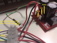
It appears you do not have the transformer connected correctly. Is there a web site to look up Nuvotem? Maybe a diagram of how you connected the transformer and some photos of your wiring would help to tell what is wrong.
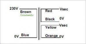
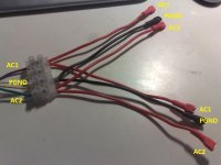
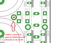
Connect black and yellow together and then to power ground on both boards. Connect the red wire to AC1 on both boards. Connect the orange wire to AC2 on both boards.
Wire cables as Bill told you then connect PGND of each board to safety ground and make a Y like this one:
Attachments
Last edited:
Hi Bill
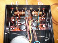
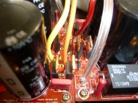
the wires goes directly from transformer to the boards
I hope you are not using that speaker wire for 240VAC mains cable.. I doubt that cable insulation was rated for that voltage. Also the hole in the chassis will chafe that insulation in no time. Better off using one of the Neutrik power-conn connectors in that tight spot.
Also the transformer is definitely wired incorrectly as they stated.
Last edited:
- Status
- This old topic is closed. If you want to reopen this topic, contact a moderator using the "Report Post" button.
- Home
- Amplifiers
- Chip Amps
- MyRefC build guide