Thanks, I just bought Morgan Jones books on amazon.
Excellent, you won't regret it..

More confused now than ever. I have an old amp and a new amp that I'm working on. They both should be the same. (they have the same passive components and tubes). On the new amp I have a russian 12ax7. I swapped it in the new amp with the old RCA 12ax7a from the old amp and it had a hugh difference in gain across the tube. With the RCA 12ax7a the oscilliscope was set to .1volts/division. When I put in the Russian 12ax7 I had to change the setting to 20mv to get the same deflection. This said to me that the 12ax7a had 5 times the gain as the Russian 12ax7. This seems to say to me that an amp has to be desigined with specific tubes from a specific manufacturer. Also with the 12ax7a the inverted voltage had the same amplitude as the non inverted where as the Russian 12ax7 had different voltage amplitudes by 20pct, which is why I was trying the old tube.
Does all this make sense?
Does all this make sense?
This said to me that the 12ax7a had 5 times the gain as the Russian 12ax7. This seems to say to me that an amp has to be desigined with specific tubes from a specific manufacturer. Also with the 12ax7a the inverted voltage had the same amplitude as the non inverted where as the Russian 12ax7 had different voltage amplitudes by 20pct, which is why I was trying the old tube.
Does all this make sense?
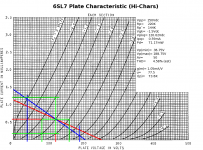
If that's the case, then that Russian 12AX7 is no good. It happens, though not to me. I did a design using RCA 6SL7 plate characteristics (see attached) and used Sovtek 6SL7s in the implementation. The design nominal gain was 25V/V/phase for an LTP, and the actual measured gain was 25 for a 0% error. The only deviation was that the Sovtek 6SL7 measured a Vgk= -2.0V against the design nominal Vgk= -1.5V (the LTP used active tail loading).
In this case, the Russian 6SL7s were true 6SL7s and conformed quite closely with the RCA characteristics.
Attachments
More confused now than ever. I have an old amp and a new amp that I'm working on. They both should be the same. (they have the same passive components and tubes). On the new amp I have a russian 12ax7. I swapped it in the new amp with the old RCA 12ax7a from the old amp and it had a hugh difference in gain across the tube. With the RCA 12ax7a the oscilliscope was set to .1volts/division. When I put in the Russian 12ax7 I had to change the setting to 20mv to get the same deflection. This said to me that the 12ax7a had 5 times the gain as the Russian 12ax7. This seems to say to me that an amp has to be desigined with specific tubes from a specific manufacturer. Also with the 12ax7a the inverted voltage had the same amplitude as the non inverted where as the Russian 12ax7 had different voltage amplitudes by 20pct, which is why I was trying the old tube.
Does all this make sense?
Something was wrong with that particular Russian tube, because of 5(!) times different gain. Also, if tubes in LTP are alive they should not show such big difference between anodes. Looks like one triode inside of the tube was almost semi-dead.
OT: I spotted "Svetlana" word in one topic, then read: "My wife is not square". Indeed, my Svetlana is not. It is for the different topic, about errors in perception.
Also my feed back is positive! Any suggestions to what I have done wrong.
You can either swap the connections to the output tube grids or you can swap the primary connections on the output transformer depending on what is more convenient, looks better, etc... Don't do both though.
I appreciate your patience. I really learning how this thing is supposed to work. I may have been wrong in my statement above on the positive feedback. The feedback goes to the cathode and screen and it is in phase with the input signal over the entire frequency range. Should this be in phase here or should it be 180 out from the input? I was thinking that since it is fed to the cathode that it should be in phase but not a larger signal than the input to the grid. The result i'm getting is a loud oscillator which dissapears when the feedback is disconnected.
Well, revrsing the primary on the output transformer worked! So I think I'm still confused on the phase of the signal going to the input cathode. Looks like it should be 180 out of phase with the input signal on the grid?
Unless you're applying the NFB as you would to an inverting op-amp (that doesn't seem to be the case here) then the signal goes to the non-inverting input, and the NFB goes to the inverting input. The two signals should be in phase.
Another way to look at it: the signal applied to the control grid causes an inverted output signal. If the input swings positive, the output swings negative. Apply NFB to the cathode: that positive-going signal causes a positive going output which bucks the input at the grid. Therefore: negative feedback.
A general question or two. In terms of voltage, how much feedback would be normal. I currently have about 50%.
If you need to increase the gain of a section, how do you do that?. Increase the voltage, reduce the load resistor? These new tubes I purchased don't have the gain that the old ones had.
If you need to increase the gain of a section, how do you do that?. Increase the voltage, reduce the load resistor? These new tubes I purchased don't have the gain that the old ones had.
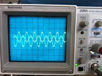
My LTP is out of balance and I can't seem how to balance it. I've tried changing load resistors but that changed the gain but the out of balance seemed to remain the same. Any suggestions would be helpful. I've attached a sketch of the circuit and a pic of the dual traces tapped at A and B on the circuit.
Attachments
Not serious at all, unless very high voltages are used. For normal audio valves there will be a brief period (few seconds) during warm-up when the cathode is hot enough to emit but not hot enough to establish a good space charge. During this period there is a risk of cathode damage from positive ion bombardment if the valve is a bit gassy. IMHO not worth worrying about.
Running with the cathode at full temperature, but no anode current, can cause sleeping sickness (cathode interface) unless the valve has a special cathode (e.g. computer-rated valves) to cope with this. Some 'stand-by' switches can create this condition.
Your LTP may be out of balance because the supply is too low or the input voltage is too high. The Mullard ECC83 LTP splitter runs the valve along a narrow channel between cutoff and grid current. If the anode voltage gets too low then in order to maintain the anode current the grid bias gets smaller and this creates grid current. This causes a voltage drop across the 1M2 resistor so the second triode is biased back. Having too high a voltage at the anode of the EF86 first stage also causes this. You can't deviate too far from the Mullard voltages (e.g. 70V at first stage anode).
Back to looking at my amp. It is running quite well with the help of you guys. I'm now trying to understand the ring (about 2 cycles) when I put a square wave input. I have noticed that the rise time as well as the 2 cycle ring seems independent of the frequency. It is underdamped and I can decrease the amplitude of the ring by increasing the feedback capacitor from .001uf to .0033uf but this will also reduce the amplitude of frequency response above 10kc. Normally it's pretty flat to 30kc. Can anyone tell me what determines the rise time, and what is the best way to tackle the underdamping and ringing amplitude.
BTW this is a standard push pull with negative feedback using an EF86, 12AX7 and 2 EL84's. The load I'm using are resistors for the testing.
BTW this is a standard push pull with negative feedback using an EF86, 12AX7 and 2 EL84's. The load I'm using are resistors for the testing.
This looks like OPT resonance. Depending on the amplitude of the ringing, I wouldn't worry too much about it. Try it out with real signals and see if there's any ringing. If not, probably good to go. (All OPTs ring to a certain extent.)
The only other option is to damp out the ringing with Zobels paralleled across each half of the primary.
The only other option is to damp out the ringing with Zobels paralleled across each half of the primary.
Square wave testing tells you more about the rise time of your signal generator than it does about the amplifier. Can you estimate the ringing frequency? Provided it is well above the audio band you can ignore it, unless it is a warning about loop instability.
Try temporarily reducing the negative feedback by increasing the feedback resistor. If the ringing increases then it is probably due to OPT resonance. If it reduces then it probably due to loop instability.
Try temporarily reducing the negative feedback by increasing the feedback resistor. If the ringing increases then it is probably due to OPT resonance. If it reduces then it probably due to loop instability.
- Status
- This old topic is closed. If you want to reopen this topic, contact a moderator using the "Report Post" button.
- Home
- Amplifiers
- Tubes / Valves
- My Wave Isn't Square.