Just a few comments. This was commonly known in the past in the audio world as "low frequency tilt". It represents a loss in low frequency response, as noted by others. All transformers exhibit this phenomena as well, and could be part of your issue, since larger transformers with more iron are required for lower frequencies. The other main culprit is roll off from your coupling caps, again as noted earlier. In other than a purely DC coupled amplifier, you will have low frequency roll off and some tilt on a square wave.
paul
paul
Just a few comments. This was commonly known in the past in the audio world as "low frequency tilt". It represents a loss in low frequency response, as noted by others. All transformers exhibit this phenomena as well, and could be part of your issue, since larger transformers with more iron are required for lower frequencies. The other main culprit is roll off from your coupling caps, again as noted earlier. In other than a purely DC coupled amplifier, you will have low frequency roll off and some tilt on a square wave.
paul
As suggested earlier, I placed a resistor for the load on the left channel and again ran a "white noise" and a "quick sweep". Attached is a pdf file of each. I don't understand this ragged plot. When I look at in with a signal generator and a tek oscilliscope, the response is rather smooth and with the roll of on low frequencies below 100hz and flat to 50kc. I wish I understood his sampling of the signal. It is obviously has some problems
with truerta or me. I'm about to give up with this approach.
Attachments
Start with a sound card loop back test before doing any other measurements and once you get a sane looking read out proceed from there. This looks like nothing more than the noise floor of your amp and/or the ADC of your sound card.
You might also want to try the demo versions of Arta and Audiotester.de..
You might also want to try the demo versions of Arta and Audiotester.de..
Start with a sound card loop back test before doing any other measurements and once you get a sane looking read out proceed from there. This looks like nothing more than the noise floor of your amp and/or the ADC of your sound card.
You might also want to try the demo versions of Arta and Audiotester.de..
Actually I did stick the output into the input and did the "sound system calibration". It's resulting output was completely flat...I suspect that was a fake output. I'm trying to get a test tool that I can make changes to the circuit and see the result more easily than using a signal generator and an oscilliscope.
Thanks I'll look at those you suggested.
Just a few comments. This was commonly known in the past in the audio world as "low frequency tilt". It represents a loss in low frequency response, as noted by others. All transformers exhibit this phenomena as well, and could be part of your issue, since larger transformers with more iron are required for lower frequencies. The other main culprit is roll off from your coupling caps, again as noted earlier. In other than a purely DC coupled amplifier, you will have low frequency roll off and some tilt on a square wave.
paul
Perhaps a slight diversion but worth an explanation.
Another way to look at it, is to think of a tube amp with a global feedback loop is really a controlled stable phaselocked loop, modulated by a signal. There is a limit to the amount of feedback and the transient response (K=damping) created by the circuit poles R & C's for any output transformer and has a bearing on sound quality.The worst part is all the parameters interact.
The problem:- An optimum squarewave quality at LF implies a high value (or no) coupling capacitance often directly conflicts with the transient response of the circuit and the amount of loop gain available.The math analysis is murderous but the practical test is more revealing. A flip in a book describing a phaselocked loop constants will show that circuit response, phase shift vs damping all interact as they do in the amplifier case. The same principles apply.
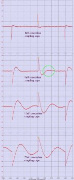
A brief pic digression of the transient response of a Williamson amp (output with differing interstage coupling cap values is shown.The 22nF illustrates too high value non settled overshoot before the next cycle and higher values towards LF subsonic oscillation and the 6n8 with green circle shows optimum circuit damping. Further reductions of value, i.e 1n0 value the circuit runs out of loop gain at the LF end and serious degrading occurs.
The contradictory nub...A high value interstage cap will give lowest LF thd figures and perhaps over-good LS damping as the global nfb value remains highest. However, repeated audio tests do show that tube amps which have a higher interstage cap value, sound muddly with higher LF intermodulation whereas an optimum cap offers the correct attack when complex LF instrumentation is replayed. This doesn't correlate with a perfect squarewave, expect tilt and also assumes the amplifier circuit at the LF end offers sufficient loudspeaker damping at the resonant frequency of the box.
This is the reason a largest transformer is best and is one of the most awkward subjects to grasp but get the Q's optimised isn't easy, but and one will have an excellent amplifier that will hit one in performance.
So the catch to throw one out; an amplifier which is slightly overdamped will require a boom box Q=1.4-2.0 to enhance the bass whereas an underdamped amp will sound nicely with a low Q speaker (0.7-1.0) often boasted for classic. The optimum complete LS Q is between 1.0 -1.4
Ones choice.
richy
Attachments
Well, I wish I understood this logic. I'll keep digging as I should be able to follow with some work.
I stuck with this TrueRTA and I think I may have it licked. I don't know what I have been doing wrong but I think it is now working well enough to be quite useful and I'm happy with the fact that what I'm seeing is agreeing with the signal generator and the oscilliscope observations. Here are the pics. Your comments would be appreciated. For the LF fall off it seems I need bigger output transformers and a larger coupling capacitor on the last stage (1st stage has none) from your comments. Currently the coupling cap is .1uf.
One pic is with a resistor load, the other with the speaker load.
Attachments
Help
I have been working on an amp and have a problem with frequency fall off. It starts about 300cps and by 30cps it's completely dead. I measure the response with an oscilliscope at pin 6 which is input to a 12ax7.
Any suggestions to try would be appreciated.
I have been working on an amp and have a problem with frequency fall off. It starts about 300cps and by 30cps it's completely dead. I measure the response with an oscilliscope at pin 6 which is input to a 12ax7.
Any suggestions to try would be appreciated.
Attachments
The "Doc1.doc" isn't openeable.
It opened for me....it's an image of part of a PCB, around the tube socket.....
I am familiar with your comments. Sorry for not explaining my problem more thoroughly. There is no transformer involved (except for the feed back) nor is there a coupling capacitor. It's just going through a EF86/6267 and the output from the tube falls way off after 300cps (measured at the plate) . By 30cps it's completly dead. Attached is a pdf of the section of the PCB that contains the tube. Plate voltage is ~180V. I can't figure why it falls so badly. I have an identical amp (without the PCB version) that is not nearly so bad and sounds quite good. I did the testing with an oscilliscope to observe the fall off. I've been staring at the layout 2 days and can't figure why I'm seeing the fall off. Hopefully you may provide some suggestions to try. Thanks
Just a few comments. This was commonly known in the past in the audio world as "low frequency tilt". It represents a loss in low frequency response, as noted by others. All transformers exhibit this phenomena as well, and could be part of your issue, since larger transformers with more iron are required for lower frequencies. The other main culprit is roll off from your coupling caps, again as noted earlier. In other than a purely DC coupled amplifier, you will have low frequency roll off and some tilt on a square wave.
paul
Attachments
Strikes me that C2 is way too small - I'd try something more like 0.022uF - 0.1uF.. R2 should be something like 1K - 10K, although in pentode mode this should not cause much HF roll-off, but it does significantly increase input noise.
Calculate the LF corner of 4700pF and 1M and this will tell where the screen grid starts to interact with the audio signal in unexpected ways. I calculated the -3dB corner at 34Hz which is the point where the 6267 stops amplifying like a pentode and the gain will plummet.
Calculate the LF corner of 4700pF and 1M and this will tell where the screen grid starts to interact with the audio signal in unexpected ways. I calculated the -3dB corner at 34Hz which is the point where the 6267 stops amplifying like a pentode and the gain will plummet.
Last edited:
C2 decouples the pentode screen grid to the cathode. Without this, the pentode acts like a triode. The relevant time constant is not C2 R3, but C2 with (R3 in parallel with screen grid impedance).
To find/estimate the screen grid impedance: take the transconductance gm at the chosen bias point and invert it, then multiply by anode current/screen current and inner mu. Get these figures from the valve data sheet. So Rg2 = mu Ia /( gm Ig2 ). It will probably come out somewhere between 10-100K.
If in the middle of this range, say 50K, your LF cutoff will be 710Hz. This explains your measurements. The circuit design is flawed.
C2 decouples the pentode screen grid to the cathode. Without this, the pentode acts like a triode. The relevant time constant is not C2 R3, but C2 with (R3 in parallel with screen grid impedance).
To find/estimate the screen grid impedance: take the transconductance gm at the chosen bias point and invert it, then multiply by anode current/screen current and inner mu. Get these figures from the valve data sheet. So Rg2 = mu Ia /( gm Ig2 ). It will probably come out somewhere between 10-100K.
If in the middle of this range, say 50K, your LF cutoff will be 710Hz. This explains your measurements. The circuit design is flawed.
A very good point, and I suspect rg2 is somewhat higher than 100K based on the reported response.. A much larger cap than I had suggested is warranted.
Oh my, it is so clear now. I don't know why I didn't see that. It makes sense. No wonder I have no low frequencies. Thanks for the help.
C2 decouples the pentode screen grid to the cathode. Without this, the pentode acts like a triode. The relevant time constant is not C2 R3, but C2 with (R3 in parallel with screen grid impedance).
To find/estimate the screen grid impedance: take the transconductance gm at the chosen bias point and invert it, then multiply by anode current/screen current and inner mu. Get these figures from the valve data sheet. So Rg2 = mu Ia /( gm Ig2 ). It will probably come out somewhere between 10-100K.
If in the middle of this range, say 50K, your LF cutoff will be 710Hz. This explains your measurements. The circuit design is flawed.
Oh my, it is so clear now. I don't know why I didn't see that. It makes sense. No wonder I have no low frequencies. Thanks for the help.
I entirely missed the part about rg2 which is something I should have been thinking about, but since I mostly use pentodes in triode connection I completely forgot that the impedance of the screen grid is not particularly high, kudos to DF96 for pointing that out, and providing a useful equation to calculate it..
Geez, what an improvment. I changed the cap to .047uf and the response on this section is great until about 20cps. The schematic I'm using is from a amp I built 40 years ago from a schematic that I found in the library. I must have made a mistake with the .0047uf. I still have some issues I'm working on later in the circuit. Thanks for your help
C2 decouples the pentode screen grid to the cathode. Without this, the pentode acts like a triode. The relevant time constant is not C2 R3, but C2 with (R3 in parallel with screen grid impedance).
To find/estimate the screen grid impedance: take the transconductance gm at the chosen bias point and invert it, then multiply by anode current/screen current and inner mu. Get these figures from the valve data sheet. So Rg2 = mu Ia /( gm Ig2 ). It will probably come out somewhere between 10-100K.
If in the middle of this range, say 50K, your LF cutoff will be 710Hz. This explains your measurements. The circuit design is flawed.
I am now stuck on the 2nd part of the amp, the 12ax7. I see that the plate of the 6267 goes directly to the grid on the 12ax7 and also through a 1m2 resistor to the 2nd grid and a .1uf capacitor to ground. I understand that the capacitor shifts the phase 90 degrees, but the amplitude is extremely small now at high frequencies but larger at low frequencies. Can someone comment on what is going here? Perhaps suggest a book I could study that would help. I did not find anything in the library on the subject.
The resistor and cap you mention form a low pass network which should have an LF corner well below the lowest frequency you want to amplify. The purpose of the network is to provide dc bias voltage to the grid equal to that on the other half of the LTP while providing something close to an AC ground at the grid at all frequencies within the amplifier's usable pass band. The input to this side of the phase splitter is via the cathode and is non-inverting.
You might want to Google "long tailed pair" The old Mullard 5-20 design notes which are probably available on line somewhere (Pete Millett site?) or Morgan Jones "Designing Valve Amplifiers" should provide the answers you seek. Possibly there is something useful on this subject on John Broskie's glassware site as well.
You might want to Google "long tailed pair" The old Mullard 5-20 design notes which are probably available on line somewhere (Pete Millett site?) or Morgan Jones "Designing Valve Amplifiers" should provide the answers you seek. Possibly there is something useful on this subject on John Broskie's glassware site as well.
- Status
- This old topic is closed. If you want to reopen this topic, contact a moderator using the "Report Post" button.
- Home
- Amplifiers
- Tubes / Valves
- My Wave Isn't Square.