Re: Re: Post #14
this tool is usefull when your 5mm (or 10mm or what you want) drill is too inacurate to drill in the small hole you did with the center punch
so, you make a little hole with this tool, and then, you can easilly adjust the big drill in the big hole")
PS: I don't know if drill is the correct word, my translator told me this. A drill is the helicoidal tool you use to drill holes
the word to word translation would be "centering drill"Rarkov said:Here we go then...
1) These are Taps (the opposite are called Dies)
2) Center punch
3) Wish I knew...What's it's function?
4) Reamer
5) Counter Sinker
Again - Amazing work!
Gaz
this tool is usefull when your 5mm (or 10mm or what you want) drill is too inacurate to drill in the small hole you did with the center punch
so, you make a little hole with this tool, and then, you can easilly adjust the big drill in the big hole
PS: I don't know if drill is the correct word, my translator told me this. A drill is the helicoidal tool you use to drill holes
millwood said:
you think too highly of yourself, Peter.
I think A/C noise is tough to get rid of. If I put the transformer close to the a/c in, I can significant shorten stray a/c wires and don't have to worry much about shielding the chips/wires.
I also think the idea of placing the toroid centrally and wire the a/c in from the bottom of the amp is quite good a suggestion. It shortens a/c wire length and provides much better balance at the same time. and it is quite unique.
As to the feet: Home Depot sells machined metal knobs for cabinet and they make good feet for an amp.
My local cabinet install can also get marble feet as well. That would be cool.
since you're talking about placing the AC inlet close to the Xformer
If it's close enough, I won't use shielded cable, but the Xformer's primary cable themselves.
Can I add a shield to this pair of cables? With an aluminium sheet, or by using a cat5 cable's shield?
Bricolo said:
since you're talking about placing the AC inlet close to the Xformer
If it's close enough, I won't use shielded cable, but the Xformer's primary cable themselves.
Can I add a shield to this pair of cables? With an aluminium sheet, or by using a cat5 cable's shield?
If you've got an aluminum shield around that section you won't need to shield the wires too. When you run the DC wires out of that section wrap +/-/gnd tightly with each other, "braid" if you will. That will keep those sections mostly under control.
Scott
No, the cables from the transformer to the ac inlet won't ben in the "PS shielded section"
Look at the link Peter Daniel gave, I want to do the same thing, but since I can't put the AC inlet at the bottom, I'll place it on the rear right. So, the AC inlet won't be in the shielded section
Look at the link Peter Daniel gave, I want to do the same thing, but since I can't put the AC inlet at the bottom, I'll place it on the rear right. So, the AC inlet won't be in the shielded section
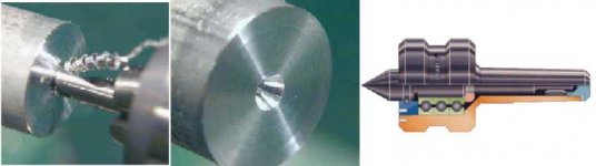
Centering drill or Center drill is a common name here in the US. The tool, while convenient for creating a pilot hole for larger drills, or even small drills to keep them from walking around, takes its dimensions from its use in the tailstock of lathes. One would put a piece of bar in the jaws (or other work holding piece) of the headstock of a lathe and the center drill in the tailstock. Fire the machine up and use the tailstock to push the stationary center drill into the rotating bar, creating a small hole with a specific chamfer at the center of the bar. Remove the center drill and replace it with a live or dead center in the tailstock to steady the work from that end. It is practically mandatory for many lathe operations.
Attached is a pic showing the center drilling operation (bar rotating, drill stationary in tailstock), the resulting hole/chamfer and a diagram of a live center, which will fit in the chamfer left by the centering drill. Now that you see the application, think of how many items you have seen with that little chamfered hole at the center. . .
Sandy.
Attachments
Sandy H. said:Centering drill or Center drill is a common name here in the US. The tool, while convenient for creating a pilot hole for larger drills, or even small drills to keep them from walking around, takes its dimensions from its use in the tailstock of lathes. One would put a piece of bar in the jaws (or other work holding piece) of the headstock of a lathe and the center drill in the tailstock. Fire the machine up and use the tailstock to push the stationary center drill into the rotating bar, creating a small hole with a specific chamfer at the center of the bar. Remove the center drill and replace it with a live or dead center in the tailstock to steady the work from that end. It is practically mandatory for many lathe operations.
Attached is a pic showing the center drilling operation (bar rotating, drill stationary in tailstock), the resulting hole/chamfer and a diagram of a live center, which will fit in the chamfer left by the centering drill. Now that you see the application, think of how many items you have seen with that little chamfered hole at the center. . .
Sandy.
Very clear explanation! Thanks!
I tried to put my aluminium plates in a lathe, to make this little chamfer, I don't know why but it didn't work
I used the centering drill with the press drill instead

Bricolo said:No, the cables from the transformer to the ac inlet won't ben in the "PS shielded section"
Look at the link Peter Daniel gave, I want to do the same thing, but since I can't put the AC inlet at the bottom, I'll place it on the rear right. So, the AC inlet won't be in the shielded section
I got it. You can either shield the cable, or run all signal wires at right angles to the AC cable when you have to take it past it. That will minimize cross talk. The AC cable itself isn't quite as bad of a problem as the DC lines which carry the half wave rectified currents related to the signal.
Scott
ScottRHinson said:
That could very well work. Shielded cables have to be used with caution, as does all grounding. One of the better articles I've seen on the subject is here:
http://www.analog.com/UploadedFiles/Application_Notes/2724253930119076254AN-347.pdf
Take a look at that.
I would recommend a sub enclosure for your transformer for sure. Be VERY careful not to create a shorted turn, or a metal loop all the way around the toroid in this case.
Scott
Very nice application note

But after having read this (everyone should read this!), I'm not so sure about the efficiency of a metal separation between the amp ant the psu, since metal is so unefficient to stop magnetic fields
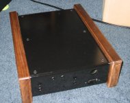
I feel sooo stupid since Peter showed me the pictures of the Pass preamp. Why haven't I put the top and bottom plates over the rear one? 
Now I can't change anything anymore, and I'm stuck with this top plate that is hard to remove.
But I found an easy solution to remove it without having to unscrew all the other sides:
Now I can't change anything anymore, and I'm stuck with this top plate that is hard to remove.
But I found an easy solution to remove it without having to unscrew all the other sides:
Attachments
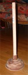
Pressure instead of suction?
You could attach an air chuck to the rear panel and use compressed air to pop the top off.
More praticle could be a pair of finger holes in the corners. The plate also sounds thick enough to tap one or more holes that could be used to scew in some sort of handle when you need to open it.
More practical could be a pair of finger holes in the corners. The plate also sounds thick enough to tap one or more holes that could be used to screw in some sort of handle when you need to open it.
An extreme solution would be to hinge one end and have dampers that would open the lid from inside when two screws are removed. In a similar fashion, a linear actuator could open the lid from a front panel control.
There are no problems, just bad suggestions from other people.
Bricolo said:
Very nice application note
But after having read this (everyone should read this!), I'm not so sure about the efficiency of a metal separation between the amp ant the psu, since metal is so unefficient to stop magnetic fields
It's not the magnetic field I would worry about with a toroidal transformer. They are inherently very low magnetic field devices because of their very construction. This is not true for other types of transformers.
It's the electric fields that could cause an issue, and this is true with any transformer. You've got to get the wires in and out somehow.
I've heard of more than one commercial mfg that allows for the transformer to be rotated before it is bolted down to make sure they have the minimum noise possible.
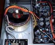
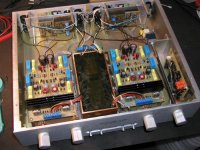
I've attached a pic of a well regarded, well measuring, $300 integrated amp. I've airbrushed out the name of the company, which was on the transformer. There is a metal sheet that runs most of the way down the side between the transformer and the signal circuitry. This piece does not provide any kind of mechanical support, the way it's mounted isn't strong enough to do that. It's not a complete Faraday cage around the transformer but they must have done tests and this fixed some sort of problem. Notice that the transformer leads come out on the far side of the signal circuitry. This isn't on accident either I bet.
On the transformer is printed:
Custom Designed Audio Grade Transformer
Excellent Distortion Characteristics
Ultra Low Magnetic Fields
High Efficiency Low Loss
I hope this helps...
Scott
Attachments
Query???
Isn't lead good for EMF shielding? I remember from the dirt track racing days of long ago that bath tub liners were 1/8"-ish lead bases which were cheap sources for lead for melting ballast. If lead is a good EMF shield, wouldn't this be a good source for the DIY guy? Am I off base? I imagine that there are other good sources for small sheets of thin lead as well.
Let me know, as I think this could be pertinant to me for future projects.
Sandy.
Peter Daniel said:This is what I did in my preamp to isolate transformers. I've built a cage out of 1/8" copper plates and filled the space with epoxy. The AC connection is also done here on the bottom panel, right beside the transformer's housing.
won't the transformer heat with this?
Sandy: I don't know about the EMI shielding capacity of lead, but it's a good nuclear shield, so there's no reason that it wouldn't also be a bood EMI shield
But lead is something that people seem to avoid (I think it's bad for health), so I think I'ill use steel (after having read ScottRHinson's link)
Some questions about the last 2 pictures:
ScottRHinson: what's at the right of the transformer, in this amp?
Does someone have an idea why the shielding plates don't go completely from one side to the other?
Peter Daniel: how did you fix the metal spacers that are between the PCBs and the chassis plates? Are they screwed? How did you do that? (I can't see how you can drill a hole and taper in in a such thin plate)
I recommend no top plate as I remember from the forum that the open top gives better sound. The open top is also good in cooling amp. I believe it is OK for you as I suppose you have no child yet.Bricolo said:
Now I can't change anything anymore, and I'm stuck with this top plate that is hard to remove.

ScottRHinson said:
I would recommend a sub enclosure for your transformer for sure. Be VERY careful not to create a shorted turn, or a metal loop all the way around the toroid in this case.
Scott
Can you explain why? I was thinking about making a faraday cage around the PS, but this makes a sort of shorted turn. What's the problem with this?
jh6you: I prefer a closed top, because of the dust. And yes, my sister has childs that are often here, so...
But I was thinking about placing a little sheet of damping material (very thin, lake a paper sheet) between all the places where 2 plates touch, this would damp the chassis vivrations
Good idea?
- Status
- This old topic is closed. If you want to reopen this topic, contact a moderator using the "Report Post" button.
- Home
- Amplifiers
- Chip Amps
- My unfinished gaincline chassis