Peter Daniel said:
You are not saying that because of my suggestion to place it in a center?
My reasoning to put it centrally is following. This is quite a big chassis by GC standards. If this is stereo amp, you should definitely use dual mono layout, with ea channel on either side and probably using side panels for heatsinking. This leaves the center space empty and it's a perfect place to mount transformer, or maybe even two. Also AC input should be placed centrally and both RCA jacks and binding posts separate on both ends of rear panel. Placing transformer centrally makes for better balanced chassis as well, not to mention having the same resonances for both channels
I'm sorry Peter, but I disagree. The cheapest way to reduce noise in an electrical system is distance...pure and simple. The best way is a well thought out grounding system and Faraday cages around the noisy and quiet parts to separate them.
I assume EMI is what you mean by the term resonance?
I have never liked a dual mono layout because it becomes much easier to make a mistake in running signals near power lines, either the full wave primary or rectified secondary lines. Those secondary currents can get all over the place if your not careful and easily set the noise and distortion floor for the amplifer.
Can it be done well? Yes. Is it much harder. Yup. If I were the builder of this amp, I'd get a big piece of aluminum bar stock and wedge it into one side of the amp. If it were the right size it could tie the side to the top and bottom thermally and even the front and back. I'd mount the gainclone chips to that, and you have a huge thermal mass to cool the chips. You can keep the chips as far away from those nasty power supply lines and realize the lowest noise floor, quietest amp you can.
Scott
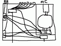
The 1st solution has the transformer on the side
advantages:
less EMI from the transformer
disadvantages:
I can't use a long axis for the volume pot
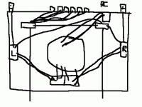
the 2nd has the transformer on the middle:
advantages:
I can use a long axis
disadvantage:
EMI
In both cases, I can place metal plates around the transformer
but it I do this, in the 2nd case, the AC inlet wires aren't in this small housing
advantages:
less EMI from the transformer
disadvantages:
I can't use a long axis for the volume pot
the 2nd has the transformer on the middle:
advantages:
I can use a long axis
disadvantage:
EMI
In both cases, I can place metal plates around the transformer
but it I do this, in the 2nd case, the AC inlet wires aren't in this small housing
Attachments
Bricolo said:The 1st solution has the transformer on the side
advantages:
less EMI from the transformer
disadvantages:
I can't use a long axis for the volume pot
the 2nd has the transformer on the middle:
advantages:
I can use a long axis
disadvantage:
EMI
In both cases, I can place metal plates around the transformer
but it I do this, in the 2nd case, the AC inlet wires aren't in this small housing
I see that you've got dual potentiometers for volume control. I'm going to modify/clarify some of my advice. Bring the power wiring straight forward from the transformer on the right side. Run it side to side along the very front of the chassis, then back to the GC amps on the left side along the left side.
Now take the speaker output straight back and exit the far corner (this is different than I said before, now that I see the layout this makes more sense). Bring the signal lines in next to the speaker out and keep them as short as possible. I'm guessing you want to have a symmetrical front panel? If you're not attached to it, put both pots on the left 1/3 of the chassis, it will still look pretty classy and you'll be able to keep the signal wiring perpendicular, or orthagonal (spelling?) to the power lines as much as you can. Make sense?
Scott
Here's a nice example of what I was talking about: http://www.hifis.com/brink/brink.htm
ScottRHinson said:
I see that you've got dual potentiometers for volume control. I'm going to modify/clarify some of my advice. Bring the power wiring straight forward from the transformer on the right side. Run it side to side along the very front of the chassis, then back to the GC amps on the left side along the left side.
Now take the speaker output straight back and exit the far corner (this is different than I said before, now that I see the layout this makes more sense). Bring the signal lines in next to the speaker out and keep them as short as possible. I'm guessing you want to have a symmetrical front panel? If you're not attached to it, put both pots on the left 1/3 of the chassis, it will still look pretty classy and you'll be able to keep the signal wiring perpendicular, or orthagonal (spelling?) to the power lines as much as you can. Make sense?
Scott
Yes, I want a symmetrical front pannel
Peter Daniel said:Here's a nice example of what I was talking about: http://www.hifis.com/brink/brink.htm
That's the layout I was also thinking about
But where is the AC inlet?
Bricolo said:
But where is the AC inlet?
It is probably coming through the bottom, directly to the transformer.
Bricolo said:
That's the layout I was also thinking about
But where is the AC inlet?
I was wondering the same thing, I don't see it. If it's under the PCB in the center, and the PCB has a good ground plane there shouldn't be much of a noise issue, and it looks to be a good implementation of that layout.
Scott
If I use a shielded AC cable from the inlet to the transformer, will it cancel 100% of the EMI?
If it's good, I could place the transformer and bridges at the center, in a little metal enclosure, and the ac inlet to the right (since the RCA inputs are in the center) connected to the transformer with a shielded cable
If it's good, I could place the transformer and bridges at the center, in a little metal enclosure, and the ac inlet to the right (since the RCA inputs are in the center) connected to the transformer with a shielded cable
ScottRHinson said:
I was wondering the same thing, I don't see it. If it's under the PCB in the center, and the PCB has a good ground plane there shouldn't be much of a noise issue, and it looks to be a good implementation of that layout.
Scott
Yes, the layout seems very good!
I'd like to build my GC like this amp.
The the only problem is: the AC inlet.
I don't have enough vertical speace to place 2 rows of RCA and an AC inlet
Bricolo said:With an input selector and a dual pot, I have 2 buttons on the faceplate
This not only look nicer, but with a 3rd one I could never use long axes for the 3 ones.
My mistake then, I thought you wanted to use separate pots for left and right channel, but I guess I got biased by the other post.
Bricolo said:
Yes, the layout seems very good!
I'd like to build my GC like this amp.
The the only problem is: the AC inlet.
I don't have enough vertical speace to place 2 rows of RCA and an AC inlet
It's not recommended to place RCA and AC connection close together. Why not do it through the bottom panel and use 90 deg offset connector for AC line?
Peter Daniel said:
My mistake then, I thought you wanted to use separate pots for left and right channel, but I guess I got biased by the other post.
Look at my 2 ugly drawings
2 pots, with one of them having much more cables connected to it
don't one look like an input selector, and the other like a volume pot?
Peter Daniel said:
It's not recommended to place RCA and AC connection close together. Why not do it through the bottom panel and use 90 deg offset connector for AC line?
Humm... I'd like little feets, so... no
But what about placing the AC connection at one side, and connect it to the Xformer with a shielded cable?
Bricolo said:If I use a shielded AC cable from the inlet to the transformer, will it cancel 100% of the EMI?
If it's good, I could place the transformer and bridges at the center, in a little metal enclosure, and the ac inlet to the right (since the RCA inputs are in the center) connected to the transformer with a shielded cable
That could very well work. Shielded cables have to be used with caution, as does all grounding. One of the better articles I've seen on the subject is here:
http://www.analog.com/UploadedFiles/Application_Notes/2724253930119076254AN-347.pdf
Take a look at that.
I would recommend a sub enclosure for your transformer for sure. Be VERY careful not to create a shorted turn, or a metal loop all the way around the toroid in this case.
Scott
Peter Daniel said:You are not saying that because of my suggestion to place it in a center?
you think too highly of yourself, Peter.
I think A/C noise is tough to get rid of. If I put the transformer close to the a/c in, I can significant shorten stray a/c wires and don't have to worry much about shielding the chips/wires.
I also think the idea of placing the toroid centrally and wire the a/c in from the bottom of the amp is quite good a suggestion. It shortens a/c wire length and provides much better balance at the same time. and it is quite unique.
As to the feet: Home Depot sells machined metal knobs for cabinet and they make good feet for an amp.
My local cabinet install can also get marble feet as well. That would be cool.
- Status
- This old topic is closed. If you want to reopen this topic, contact a moderator using the "Report Post" button.
- Home
- Amplifiers
- Chip Amps
- My unfinished gaincline chassis

