Hi
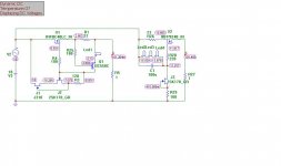
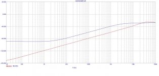
I made a simulation of a constant current source from the schematic reg-v2n-5k, MicroCap is a simulation software. Here are the results. Is anyone besides me simulate the CCS? Why so much performance decrease with increasing frequency? I made a simulation for Salas's V1 CCS and compared with Ikoflexer CCS...
I made a simulation of a constant current source from the schematic reg-v2n-5k, MicroCap is a simulation software. Here are the results. Is anyone besides me simulate the CCS? Why so much performance decrease with increasing frequency? I made a simulation for Salas's V1 CCS and compared with Ikoflexer CCS...
Attachments
Viktor, what are you trying to achieve? In the regulator the CCS works together with the shunt part; if I were you, I'd compare them with the same shunt circuit. You can then simulate ripple rejection and output impedance.
Thank's Iko!
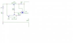
What is your opinion about changing the 2N5088 and led diodes in CCS with TL431? Simulation shows better PSSR with TL431...
Noise and stability would be my concerns. But you haven't answered what your final target is. I don't really understand why you're paying more attention to the CCS. The CCS that I use or the CCS that Salas uses in his version 1.2 both have high performance and are stable, when used in the shunt regulator. If you want a CCS for some other application it would be better to design it specifically for that app.
Noise and stability would be my concerns. But you haven't answered what your final target is. I don't really understand why you're paying more attention to the CCS. The CCS that I use or the CCS that Salas uses in his version 1.2 both have high performance and are stable, when used in the shunt regulator. If you want a CCS for some other application it would be better to design it specifically for that app.
My concern was that I had made a simulation of your and salas CCS, your CCS had a better performance but it not looked like salas simulation in terms of linearity pssr from 20Hz-50kHz, my concern was that with increasing frequency and fell pssr, I thought it should look linear like salas ccs...
I made a simulation of the complete reg, CCS + shunt, it looks fantastic. Will start the next day to drawing board. Otherwise, I plan to have this be a power supply for the preamplifier.Just seems that I have to use some replacement transistors because in my country can not be found 2n5088, J201, mpsh81, only to order them from "mouser." Maybe there are, who knows! I will read this topic to see whether there was a question of a replacement transistor...
I have explored using the TL431 in this regulator and in the end I decided it wasn't worth the trouble, but you should decide for yourself.
Regarding parts replacement, to save you some reading: the J201 can be replaced with a 2SK170 if you change the voltage reference resistor values. You can use a BC550 instead of the 2N5088 without a problem. The mpsh81 is more difficult to replace with something else because it is an RF part and I think it helps to stay fast. A good layout is very important for this regulator as well. If you don't want the headache you can just build the Salas simplistic v1, which is excellent, in my opinion. And don't forget his newer one, has a really good CCS and should be also as fast as this one because it uses the bjt helper on the shunt mosfet, just like this reg.
You can use other mosfets as well; just watch the heat dissipation. Best to choose those with low capacitance.
I have explored using the TL431 in this regulator and in the end I decided it wasn't worth the trouble, but you should decide for yourself.
Regarding parts replacement, to save you some reading: the J201 can be replaced with a 2SK170 if you change the voltage reference resistor values. You can use a BC550 instead of the 2N5088 without a problem. The mpsh81 is more difficult to replace with something else because it is an RF part and I think it helps to stay fast. A good layout is very important for this regulator as well. If you don't want the headache you can just build the Salas simplistic v1, which is excellent, in my opinion. And don't forget his newer one, has a really good CCS and should be also as fast as this one because it uses the bjt helper on the shunt mosfet, just like this reg.
You can use other mosfets as well; just watch the heat dissipation. Best to choose those with low capacitance.
Ok, thank's for the proposed replacement transistors and suggestions for TL431. What's with 2N3819? Worries me a little bit shunt because in the simulation temperature change of 10 degrees shows that the output voltage falls 1V, for 20 degree 2V under Vout...
I made Salas V1 successfully for +/-24V DC,100mA, and would like something a little different now to try.
If you need a circuit that can deal with 10 degree temperature change you'll have to look elsewhere or redesign and use a different voltage reference and CCS. As is if the temperature in the box doesn vary wildly it will stabilize after about two minutes and won't change much from there.
Hi, guys,
I have been as busy as Ikoflexer and anyone else, or worse, have not had more than 20 minutes in the past 2 months checking the diyAudio. Anyway, I have now a reference level system running.")
Some guys spread the news and prompted some of the most prominent HiFi big boys in Sydney to come to audition my system. I also received an interview for an article for the Australian HiFi magazine. etc. These did not make me a happier person but last night I did have some smiles on my face when I saw my friend, Paul, a recording master engineer, who has previously recorded for the BBC symphony, was so pleased with my system. He played some of his own recordings and told me that what he heard from my system minic exactly his memory of the recording sessions, with musical instruments in exact placements in exact distances. The funny thing is that he said he no longer heard music but every single recording fault he made in his recordings - he said that the system revealed everything. He invited me to visit his recording studio, will send his mate (who had two PhDs in psychoaccoustic and in relevant field) to help redesigning my room accoustic for my system, etc. It got me so excited.
I am making no secrete - There are 3 individual Ikoflexer's 5k CCS shunt regs running in my preamp/active XO circuits, the circuit layout was likely my own 6th revision of Ikoflexer's regs. Be warned though, if you do the wrong thing and add an inch to some track that you shouldn't, you can ruin the sound. If you do it properly, nothing beats it. Low inductance and low impedance at high frequency (via film cap bypass) throughout the entire circuit from the transformer output up to the load is the key.
Ikoflexer and Salas -
Regards,
Bill
I have been as busy as Ikoflexer and anyone else, or worse, have not had more than 20 minutes in the past 2 months checking the diyAudio. Anyway, I have now a reference level system running.
Some guys spread the news and prompted some of the most prominent HiFi big boys in Sydney to come to audition my system. I also received an interview for an article for the Australian HiFi magazine. etc. These did not make me a happier person but last night I did have some smiles on my face when I saw my friend, Paul, a recording master engineer, who has previously recorded for the BBC symphony, was so pleased with my system. He played some of his own recordings and told me that what he heard from my system minic exactly his memory of the recording sessions, with musical instruments in exact placements in exact distances. The funny thing is that he said he no longer heard music but every single recording fault he made in his recordings - he said that the system revealed everything. He invited me to visit his recording studio, will send his mate (who had two PhDs in psychoaccoustic and in relevant field) to help redesigning my room accoustic for my system, etc. It got me so excited.
I am making no secrete - There are 3 individual Ikoflexer's 5k CCS shunt regs running in my preamp/active XO circuits, the circuit layout was likely my own 6th revision of Ikoflexer's regs. Be warned though, if you do the wrong thing and add an inch to some track that you shouldn't, you can ruin the sound. If you do it properly, nothing beats it. Low inductance and low impedance at high frequency (via film cap bypass) throughout the entire circuit from the transformer output up to the load is the key.
Ikoflexer and Salas -
Regards,
Bill
Hey Bill,
You put a lot of effort into that system, I'm glad it's paid off. Thanks for stopping by.
It's so difficult to find your latest "configuration" in this long thread. I wish there was a place where we could have the latest findings as a summary. All the little tricks that make it work best.
We should all buy Salas a beer (each) He started it all! Salas
You put a lot of effort into that system, I'm glad it's paid off. Thanks for stopping by.
It's so difficult to find your latest "configuration" in this long thread. I wish there was a place where we could have the latest findings as a summary. All the little tricks that make it work best.
We should all buy Salas a beer (each)
He started it all! SalasHey Bill,
It's so difficult to find your latest "configuration" in this long thread. I wish there was a place where we could have the latest findings as a summary. All the little tricks that make it work best.
QUOTE]
A summary thread for this and Salas' thread(300 pages!) would be nice. So you can have a quick overview of the various configs and the recommended parts. I really get lost sometimes
Thanks for your kind words.
I am happy to share but however don't know how. I will do my best.
There are too many parameters affecting the sound and it is strongly depending on the load as well. What suits me may not suit you. What suits me this time may not suit me next time. For example, my load is opamps. If your load is different then the local bypass requirements would be different. We should treat the load as well as the regulator as parts of the circuit.
When I had some longer track in one of my earlier builds, I had to use a 22uF electrolytic at the load so not to have some tiny ripples introduced and a film cap at that time caused some ripples, possibly due to the input capacitance of the opamps the the wire inductance, as I previously reported. Now I have the shortest possible track from the output of the MOSFET to the load using 16awg wires. I can now use 4 x 1.1uF MKP only bypass right at the load and the measurement shows the rails are quiet! and subjectively it sounds a lot better. Having an electrolytic output cap at the regulator side along with 6 x 1.1uF MKP is sonically fine. Move that electrolytic cap to the load side and the sound becomes unacceptable to me, though my scope does not show any differences. It requires a lot of experiments and hours of listening to determine the best outcome for a single implementation of a cap change, a track change, etc.
These would be true for any implementations, I guess:
1) As engineers tell us, from the transformer output to the first filter cap the resistance should be as close to 0 as possible. Use thick wire on the rails throughout.
2) Using the Fairchild diamond stealth diodes as rectifiers, in my implementation it would still require 0.022uF across the diodes. I tried 470p, 1n, 1n5, 2n2, 4n7, 10n, 22n, 33n and 56n to fixed on the 22n value. It sounds best. The scope is not good enough to show the difference.
3) In theory the regulator may not care about the output impedance of the raw supply. In subjective listening, it makes a huge difference. I placed 3,300uF FC and 1,500uF ZL and 6 x 1.1uF MKP directly at the input of the CCS. A track of 10cm between the caps to the CCS input would give a shrilling sound at high frequencies. Would you like to get rid of that "Zz...." in female vocals?
4) Remote sensing is a must. Even so, keep the track from the output MOSFET to the LOAD as short as possible. It does make a difference subjectively.
5) Keep tracks as short as possible to keep inductance low for smooth high frequency response. This applies to the entire regulator / load circuit layout.
6) MKP local bypass is needed right at the load. With my latest layout, I have no resonances whatsoever when the load is less than 6cm away from the regulator output. However, adding some local bypass film caps smooths the sound. For a load that is longer than 12cm away from the regulator output, 4 x 1.1uF MKP at the load eliminates any ripples.
7) Caps make a strong influence on the sound, regardless of their positions. I use Panasonic FC (Raw supply only), Rubycon ZL and Visual MKP. I tried others, even in the raw supply, but did not like them.
8) The rest in my audio chain must be of the same high standard in order for me to be able to identify those differences. A system can only sound as good as the worst component.
9) Even for a single opamp, 173mA CCS current makes it sound good / OK. Increase it 213mA achieves at least one level up sonically. This is the maximum my heatsinks allow.
Happy building.
Regards,
Bill
OK. One more piece of good news:
I had a "HiFi" / music listening gathering at my home the weekend before the last one and I also organized some live music as well - Beethoven Sonata, etc. Among the guests was Gary Stravou, the conductor of Balmain Sonfonia, a Sydney based full symphony orchestra. He used to play violin. On that day, he played his favourite CD (Bach Violin Sonata, SACD by Pentatone) on my system and he commented that the violin was "very realistic". Those were his words.
Of course, that is how the worst component of my system sounds, as a whole system can only sound as good as the worst component. So you can imagine how bad the Iko reg sounds. Mind you, the worst component in my system is probably the CD player, followed by the power amps.
One thing I do want to "improve" on the Iko reg - I found running on 213mA the sound is a lot better than running on 170mA. So I am planning to have a new chassis with new heatsinks to run them to perhaps up to 0.5A. I have not worked out how it can be done with so much heat to be dissipated (3 regulators in total) while I have to keep the MOSFETS to the load to the absolute minimin distance I can manage (currently 30mm). Mounting the MOSFETS directly on the chassis may be an option, but would be so inconvenient if I need to modify the circuit boards, replacing components, etc.
Regards,
Bill
Keantoken,
Great work! It is very much appreciated.
Just half an hour ago I did some measurements on my Marantz SA11S1 CD player. I was acting on Keantoken's advice to find out how high the ripples are after the rectifiers so that I can calculate what capacitor value to use in front of the K-Multiplier and how many diodes to make up the diode string in the K-Multiplier.
I have been very much honoured that Keantoken designed this for me on my request, to get rid of the 3mV ripples on the rails of my Marantz, as I can not house the superior Iko reg inside the Marantz due to heat dissipation.
Guess what I found half an hour ago? Strange readings prompted me to investigate. A fuse for one of the two transformer outputs was found broken! So the DAC / output circuit of the CD player has been running using only one of the two transformer windings. Would it be the cause of the 3mV ripples on the rails? It may only require an easy fix - replacing the fuse.
I will buy the fuse tomorrow and see if it fixes the problem. In any case, I believe if I replace the 4,700uF capacitor on the Marantz with the K-Multiplier, it will increase the sonic performance, as adding the K-multiplier increases the ripple rejection from about 75dB to 147dB. However, my investigation tonight on the Marantz PSU board shows that there will be a lot of work involved. The whole section of rectification will also need to be replaced. So I won't do it tomorrow. I need to plan carefully and design a new board before I do this mod.
Congratulations, Keantoken! from the ripple rejection figures and the output impedance graphs you sent me I understand that you have achieved something special. I have seen no other C-multipliers having such low output impedance. You have giving us a great gift, something I will definitely put into my "schematic" bin, that will be used whenever needed.
One day I may try it before the Iko reg. but I know well the Iko reg has 3 digit dB ripple rejection so nothing is needed in front of it.
Best regards,
Bill
Great work! It is very much appreciated.
Just half an hour ago I did some measurements on my Marantz SA11S1 CD player. I was acting on Keantoken's advice to find out how high the ripples are after the rectifiers so that I can calculate what capacitor value to use in front of the K-Multiplier and how many diodes to make up the diode string in the K-Multiplier.
I have been very much honoured that Keantoken designed this for me on my request, to get rid of the 3mV ripples on the rails of my Marantz, as I can not house the superior Iko reg inside the Marantz due to heat dissipation.
Guess what I found half an hour ago? Strange readings prompted me to investigate.
A fuse for one of the two transformer outputs was found broken! So the DAC / output circuit of the CD player has been running using only one of the two transformer windings. Would it be the cause of the 3mV ripples on the rails? It may only require an easy fix - replacing the fuse. I will buy the fuse tomorrow and see if it fixes the problem. In any case, I believe if I replace the 4,700uF capacitor on the Marantz with the K-Multiplier, it will increase the sonic performance, as adding the K-multiplier increases the ripple rejection from about 75dB to 147dB. However, my investigation tonight on the Marantz PSU board shows that there will be a lot of work involved. The whole section of rectification will also need to be replaced. So I won't do it tomorrow. I need to plan carefully and design a new board before I do this mod.
Congratulations, Keantoken! from the ripple rejection figures and the output impedance graphs you sent me I understand that you have achieved something special.
I have seen no other C-multipliers having such low output impedance. You have giving us a great gift, something I will definitely put into my "schematic" bin, that will be used whenever needed.One day I may try it before the Iko reg. but I know well the Iko reg has 3 digit dB ripple rejection so nothing is needed in front of it.
Best regards,
Bill
- Status
- This old topic is closed. If you want to reopen this topic, contact a moderator using the "Report Post" button.
- Home
- Amplifiers
- Power Supplies
- My take on a discrete shunt voltage regulator