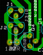
Iko, on your latest board layout, it looks like the trace from J1's source
is going to J2's source instead of the drain.
Right, good catch, thank you! I had used the wrong footprint for the J310, DGS instead of DSG. Attached is the fix.
Attachments
O.K. If I go with individual regs, I may as well max the isolation. Thanks
stormsonic.
Iko, on your latest board layout, it looks like the trace from J1's source
is going to J2's source instead of the drain.
I would be interested in knowing how you would do the grounding work. Your ground coming from the raw supply must branch out to 6 regs. At the local star point for each reg (sensing point) it is the quietest point or the zero volt reference point. You would connect this point to the chassis. So there you have 6 seperate parallel paths from the raw supply common to the chassis.
Now you can't really have all 6 regs match 100% in CCS and voltages so the zero volt reference point for each reg is different. Some noise will be developed in some branches.
If all of your 6 regs are powering up the same circuit it is even more problematic. I will be using 3 regs, each for different branch: tweeter, midrange and woofer. Even so, I have had enough headache with it.
In any case, if multiple regs are necessary, it must be designed in such a way that the zero volt reference point for each regulator be kept as close as possible.
Wires do have resistance and inductance.
The idea of using multiple regs is to shorten the wires from the star point to the load to reduce noise. But if it introduces more probelm than it solves then a balance must be found.
on the schematic for the 3.3v reg, what input voltage works best?
Designed for 5V input voltage, output 3.3V, loads up to 80mA. Q1 and Q7 need some cooling (big PCB pad acting as cooler).
It will work with higher input voltage and higher current, but calculate power dissipation on Q7 and Q1 and use different transistors if needed.
LED's: Green, red, yellow, 3mm or 5mm or SMD type, anything will be OK.
Output voltage can be calculated: Q3 Vbe + D1 Vf + R17 voltage drop = output voltage
Example:
Q3 Vbe = approx. 0.67V
D1 Voltage forward = 2.1V (depends on diode used)
R17 voltage drop = I(current) * R(resistance)
0.67V + 2.1V + 0.53 = 3.3V
To get 0.53V voltage drop on R17 (100R), current through resistor must be 5.3mA. Current through R17 depends on current through J5. Current through J5 depends on resistor R15. (Base current for Q3 can be left out from equation).
If resistor R15 is 100R, current through J5 and through R17 will be approx. 3.5mA. This will give us 0.35 voltage drop on R17. Output voltage will be lower than 3.3V. In this case R17 value should be increased to 150R, 3.5mA through 150R = 0.525V.

I built a LM317/337 pre-regulator a while back but had not have the time to try it.
I tried it today replacing the LRCLRC raw supply. It did not sound any better. However, when I put the pre-regulator in front of the LRCLRC, then the CCS-shunt, the improvement was obvious. So both stay. With the pre-regulator, I have only 10V available for the CCS now. But then the CCS hardly needs to do any regulation any more. 10V enough?
I tried it today replacing the LRCLRC raw supply. It did not sound any better. However, when I put the pre-regulator in front of the LRCLRC, then the CCS-shunt, the improvement was obvious. So both stay. With the pre-regulator, I have only 10V available for the CCS now. But then the CCS hardly needs to do any regulation any more. 10V enough?
check the ripple at the input to the pre-reg.
Most DMMs can measure the ripple at approximately the rms value for the basic 50 or 60Hz waveform. Multiply this by 3 to obtain a rough estimate of Ripple voltage peak to peak.
You should check this when mains is at it's lowest and current draw is at maximum. Fortunately the CCS+Shunt has a near constant current draw.
Your DMM reads DC average level. The ripple is superimposed on this. Minimum input voltage to the pre-reg is worst case average minus half of it's associated Vpp.
Allow for the regulator drop out at the actual output current and ensure the pre-reg output voltage is less than (Min DC average) - (Vpp/2) - (drop out) - (0.5V)
This becomes the worst case input to the CRC. allow the same drop as you have measured at present. This voltage drop hardly changes due to the CCS.
Ideally you want ~10V headroom above the reg output voltage, but we have already been told that the reg works adequately with 6V of headroom.
I suggest you aim for ~10V with nominal mains supply and >6V when mains is at minimum supply voltage. But the pre-reg complicates this. Which is worse? the pre-reg dropping out in the low voltage dips of the ripple or setting the pre-reg lower and running with 8V of headroom?
Since I have 28.6V after the rectifiers and I only need 15V at the output I think I should have enough headroom to play with.
Further listening made me think again if it is actually better. It appears the midrange is better but the treble may not be so. Too many parameters and too many changes have been made.
I guess next when I have time I may try LRCLRCLRCLRC, keeping the total C to be the same but doubling the L. Those 470uF chokes cost under $2 each so as long as I have space they should work fine. I modelled it with PSU2 and the ripples are so low only in 10s of mV region and I still have about 10V for the CCS because each 0.5R does not cause much voltage drop. With LRCLRCLRCLRC, even at 2kHz the ripples should be 166dB down. How much better than that do we want?
I am wondering if the sort of sound improvement I first perceived was due to the longer ground wire it introduced. The regulator has very high ripple rejection. So as the pre regulator and the LRC filter. Theoretically it should not be perceivable. But I am afraid in reality, the ground point closer to the rectifier is the point that is dirtier. Adding more stuff now with doubling the length of the ground wire can make the circuit ground point quieter, and that may introduce some audible difference.
Last edited:
Happy DIYing! my time for DIY is very limited these days but still when I have a chance I come back to it, since my project has been put aside but I have to finish it.
I gave some thoughts on my use of the LM317/337 and LRCLRCLRCLRC and how they sound different, etc. and I guess I may have worked out the answer, yet to be proved by doing some sodering this weekend.
I recalled one of my private exchanges with Ikoflexer he mentioned: "Interesting, bypass caps at the very input of the regulator seem to add stability when driving a capacitive load. I tried a 10nF || 100nF || 47u".
Previously, it was assumed that the CCS-shunt did not care for having a low AC impedance at its input. I think adding 10nF || 100nF || 47u at the input effectively provides a low impedance at higher frequencies.
Yesterday, I added 1uF || 10nF || 68pF to the already existing 1500uF at the input of the regulator, and there was a definite improvement to the sound. I previously said that the regulator sounded excellent, although my system had some small level of high frequency noise I could not get rid of. This experiment appeared to have reduced that quite a bit, so it led me think that the regulator requires a low AC impedance at its input.
The reason that my LM317/337 pre reg alone did not sound good was possibly due to the low capacitance hence high impedance at the input of the regulator, especially at higher frequencies.
I have dozens of Rubycon ZL 2200uF 25V but have run out of 1500uF 35V. So today I am planning to use the LM317/337 preg to lower the voltage to 24V, then have LRCLRC, with the last C = 2 x 2,200uF || 2 x 1.1uF || 10nF || 68pF. This should give a low impedance at all frequencies to the regulator, although the voltage drop across the CCS will be 8V only. With the pre-reg and large capacitance, I can't see any possibility that the voltage can drop, so I hope 8V across the CCS is OK, as Ikoflexer said that 6V was the minimum. The question is that he changed the CCS in 5k so it may be different now. I will see how this sounds and report back.
I gave some thoughts on my use of the LM317/337 and LRCLRCLRCLRC and how they sound different, etc. and I guess I may have worked out the answer, yet to be proved by doing some sodering this weekend.
I recalled one of my private exchanges with Ikoflexer he mentioned: "Interesting, bypass caps at the very input of the regulator seem to add stability when driving a capacitive load. I tried a 10nF || 100nF || 47u".
Previously, it was assumed that the CCS-shunt did not care for having a low AC impedance at its input. I think adding 10nF || 100nF || 47u at the input effectively provides a low impedance at higher frequencies.
Yesterday, I added 1uF || 10nF || 68pF to the already existing 1500uF at the input of the regulator, and there was a definite improvement to the sound. I previously said that the regulator sounded excellent, although my system had some small level of high frequency noise I could not get rid of. This experiment appeared to have reduced that quite a bit, so it led me think that the regulator requires a low AC impedance at its input.
The reason that my LM317/337 pre reg alone did not sound good was possibly due to the low capacitance hence high impedance at the input of the regulator, especially at higher frequencies.
Ideally you want ~10V headroom above the reg output voltage, but we have already been told that the reg works adequately with 6V of headroom.
I suggest you aim for ~10V with nominal mains supply and >6V when mains is at minimum supply voltage. But the pre-reg complicates this. Which is worse? the pre-reg dropping out in the low voltage dips of the ripple or setting the pre-reg lower and running with 8V of headroom?
I have dozens of Rubycon ZL 2200uF 25V but have run out of 1500uF 35V. So today I am planning to use the LM317/337 preg to lower the voltage to 24V, then have LRCLRC, with the last C = 2 x 2,200uF || 2 x 1.1uF || 10nF || 68pF. This should give a low impedance at all frequencies to the regulator, although the voltage drop across the CCS will be 8V only. With the pre-reg and large capacitance, I can't see any possibility that the voltage can drop, so I hope 8V across the CCS is OK, as Ikoflexer said that 6V was the minimum. The question is that he changed the CCS in 5k so it may be different now. I will see how this sounds and report back.
Last edited:
OK. Did the changes. Also added a 2n2 to the Vref cap making it 56uF || 1.1uF || 2n2.
Waiting for running in the caps before making a verdit. So far so good. I measured no resonances whatsoever.
I think the remaining thing is to work out the best combinations of parallelled caps. Traditionally, people use the 1/10th rule, e.g. 1uF || 0.1uF || 10nF, etc. I am wondering if the values are too close.
although the voltage drop across the CCS will be 8V only. With the pre-reg and large capacitance, I can't see any possibility that the voltage can drop, so I hope 8V across the CCS is OK, as Ikoflexer said that 6V was the minimum. The question is that he changed the CCS in 5k so it may be different now. I will see how this sounds and report back.
Bill, you may want to try the p-channel mosfet CCS like Salas uses. I sent you a schematic once. Because that CCS is referred to GND it will help you.
Thanks. Since it is new stuff I am afraid of spending too much time working it out so I am giving it a miss. The current design is proven so I am sticking with it.
My finding is that the pre-reg does not do any better than without it. So it is now out. The raw LRCLRCLRC thing is back on. I am getting 28V+ before the regulator so 13+V drop on the CCS that is according to your spec. Tried the larger capacitance but found the critical thing is really to use the proper multiple bypassing. I am talking about the capacitors before the regulator. The 1.1uF film cap improved the sound quite a bit but it is still not good enough for higher frequencies. Paralleled with 0.1uF and the value is apparently too high. Reduced to 2n2 makes it much better and 1n is too low. I need to find the optimal value and this can only be done by exhaustive tests. The scope shows nothing in this department but changing the values obviously changes the sound. I have ordered some 4n7, 2n2, 1n5, 1n and 470p for the tests. I might still need to choose a low pf value too.
Of course, I am only talking about optimization here to squeeze every bit out of it.
Could you please update your schematic by putting the ideal Idss of the jFETs on it? My build is very slow because of lack of time but will get to it in the next a few days.
- Status
- This old topic is closed. If you want to reopen this topic, contact a moderator using the "Report Post" button.
- Home
- Amplifiers
- Power Supplies
- My take on a discrete shunt voltage regulator