actually it s more 200ma per channel so i d like 400 to 800ma. and +-30V would be preferable. but if there are odds that it s a bit more difficult to build than salas shunt, i ll take the latter. honestly, it was pretty much heads and tail when i chose which one to build.. as you said and as i read, i shouldnt worry about the performance so...
still salas shunt cant do 3.3v as he told me. so you are my last hope")
still salas shunt cant do 3.3v as he told me. so you are my last hope
Last edited:
I think this shunt reg would make a nice upgrade over the linear +/- 15v
supply in my active xover.
The xover has all its buffer and pass stages built around a discrete
opamp (6 per ch), and I'm considering individual pos/neg shunt regs for
each opamp.
But I'm wondering if this reg's low output imp. and remote sensing largely
cancels out any benefits gotten from individual regulators.
I'm sorry, the individual regs I was referring to is your design.
So, I was considering putting smaller 40 mA regs at each of the 6 opamps
instead of one 240mA reg per channel.
I'm just not sure if there was any point to doing this since, if I understand correctly, the remote sensing makes the different length runs from each opamp to one main reg somewhat irrelevant.
Hi, guys,
I am spending 90% of my SPARE time on my "bread and butter" work now and only 10% on DIY. But will cut the boards today and build 3 x +/-15V regulators for my active XO in the following weeks. I think if ppap64 wants 6 regulators for 6 opamps it may be a bit overkill. I can tell you my result in about a couple of weeks time.
Ikoflexer,
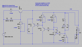
Here is one suggestion: we have gone through those before but I think it is very convinent if you inidcate the ideal Idss (or Idss range) of the jFETs directly on the schematic so that we don't need to go back to the previous over 1000 posts trying to dig out the information, which is something I have to do now. I remember for J2 and J4 they would be 7mA to 8mA, or not?
Regards,
Bill
I am spending 90% of my SPARE time on my "bread and butter" work now and only 10% on DIY. But will cut the boards today and build 3 x +/-15V regulators for my active XO in the following weeks. I think if ppap64 wants 6 regulators for 6 opamps it may be a bit overkill. I can tell you my result in about a couple of weeks time.
Ikoflexer,
Here is one suggestion: we have gone through those before but I think it is very convinent if you inidcate the ideal Idss (or Idss range) of the jFETs directly on the schematic so that we don't need to go back to the previous over 1000 posts trying to dig out the information, which is something I have to do now. I remember for J2 and J4 they would be 7mA to 8mA, or not?
Regards,
Bill
Will do Bill, good suggestion!
ppap, people have reported elsewhere that individual regulators make a positive difference. I haven't tried it myself, but at least some top end devices do it that way. Another way to do it is to have one common CCS module that feeds a bunch of individual shunts.
ppap, people have reported elsewhere that individual regulators make a positive difference. I haven't tried it myself, but at least some top end devices do it that way. Another way to do it is to have one common CCS module that feeds a bunch of individual shunts.
Will do Bill, good suggestion!
ppap, people have reported elsewhere that individual regulators make a positive difference. I haven't tried it myself, but at least some top end devices do it that way. Another way to do it is to have one common CCS module that feeds a bunch of individual shunts.
Better to have 1 common preregulator, (LM317 or cap multiplier or.....anything), feeding individual CCS + shunt.
Different circuits (loads) will interfere with each other + sharing current paths is not good. CCS will provide isolation between those loads and should not be common. Loads should not see each other, they must be isolated.
- Status
- This old topic is closed. If you want to reopen this topic, contact a moderator using the "Report Post" button.
- Home
- Amplifiers
- Power Supplies
- My take on a discrete shunt voltage regulator