I don't know how far back the ccs fed shunt regulator design goes, but Erno Borbely and Are Waagbo should be noted as using this topology, salas has also made modifications and arrived at his v1 and v1.1 design. The salas design and variations can be found in this thread. I'd like to especially thank salas; his circuit and attitude inspired me, and his comments were always helpful.
The schematic below uses the same topology as these noted and proved designs, with some modifications by yours truly. It seems to perform pretty good. My modifications address three aspects: lower the noise of the regulator itself, keep the good psrr of these other designs, and extend the bandwidth of the output impedance to higher frequencies. Low output impedance at high frequencies depends a lot on the actual implementation and board layout, but the design at least allows for very good performance. All this while maintaining the parts number and the complexity of the circuit low.
Using the active devices in the schematic the output voltage can be set anywhere from about 8V to almost 40V. Using a logic level mosfet (e.g. PHP3N20L) for M1 allows an output voltage of 5V which is particularly popular with DACs. The supplied current depends on the heat dissipation of M1 and M2. Using the IRFBC40 and huge heat sinks my prototype successfully reached 20V at a bit more than 3A total current. Other mosfets can also be used.
The design has the potential of very low output impedance up to pretty high frequencies. This means that layout and the choice of some parts is important to get a stable implementation. Q2, Q3, and C2 are probably the more important parts that affect stability.
The values of R7, R2, C3, R10, R11, R9, C2, and C1 need to be tweaked for one's own specific needs. Do not take the values shown in the schematic as values that will work out of the box. The schematic is pretty insensitive to reasonable tolerance in resistor and capacitor values.
The voltage reference is comprised of J2, R10, R11, and R9. R10 sets the current through the reference. My preference is for about 250uA. R11 and R9 set the output voltage, and they don't have to be exactly equal.
My preference is to run the mini-CCS formed by J4, J3, R7, and R2 at about 500uA. The voltage drop across R2 biases M2 and sets the current limit of the entire regulator.
R6 is a sense resistor that does not belong in the final circuit. It is useful in the initial stage when the shunt current is set to the desired value, by adjusting R2. The current through the shunt mosfet M1 is equal to the voltage across R6 divided by the value of R6. A good rule of thumb is to set this current to 10 to 20% of the load current. It's just a rule of thumb. Some people like to set this current much higher, because it has been reported sound better.
If anyone is interested in building it I plan to be around to answer questions. Sometime in the future I hope to offer some sort of official PCB and detailed HOWTO document.
Disclaimer: there are no guarantees of any kind, implicit or explicit.
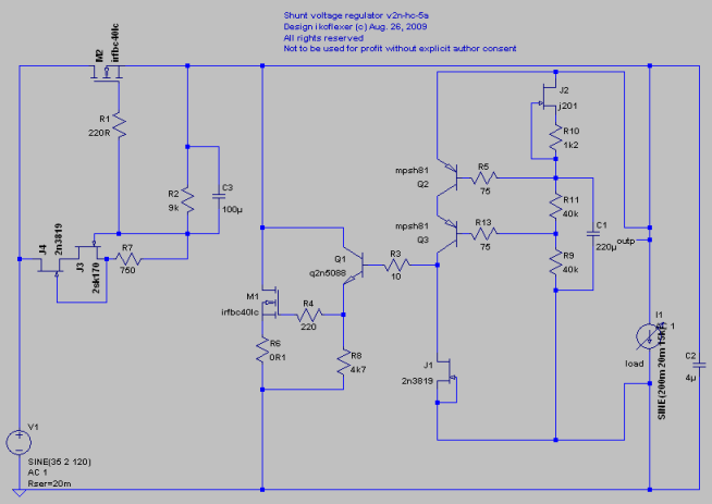
Here is the positive rail
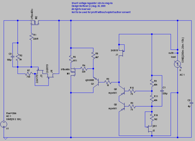
the negative rail
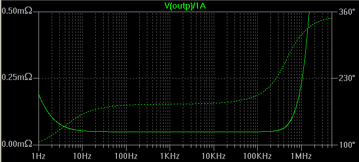
the simulated output impedance
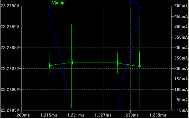
and the step response to a pretty extreme square wave of 0.5A
With some small modifications this circuit can be made to provide higher current and higher voltages for power amps, for instance. Also, it can be made to supply B+ voltage to tube preamps/amps. In the future I will probably publish schematics for such variations in this thread.
Thanks for looking.
The schematic below uses the same topology as these noted and proved designs, with some modifications by yours truly. It seems to perform pretty good. My modifications address three aspects: lower the noise of the regulator itself, keep the good psrr of these other designs, and extend the bandwidth of the output impedance to higher frequencies. Low output impedance at high frequencies depends a lot on the actual implementation and board layout, but the design at least allows for very good performance. All this while maintaining the parts number and the complexity of the circuit low.
Using the active devices in the schematic the output voltage can be set anywhere from about 8V to almost 40V. Using a logic level mosfet (e.g. PHP3N20L) for M1 allows an output voltage of 5V which is particularly popular with DACs. The supplied current depends on the heat dissipation of M1 and M2. Using the IRFBC40 and huge heat sinks my prototype successfully reached 20V at a bit more than 3A total current. Other mosfets can also be used.
The design has the potential of very low output impedance up to pretty high frequencies. This means that layout and the choice of some parts is important to get a stable implementation. Q2, Q3, and C2 are probably the more important parts that affect stability.
The values of R7, R2, C3, R10, R11, R9, C2, and C1 need to be tweaked for one's own specific needs. Do not take the values shown in the schematic as values that will work out of the box. The schematic is pretty insensitive to reasonable tolerance in resistor and capacitor values.
The voltage reference is comprised of J2, R10, R11, and R9. R10 sets the current through the reference. My preference is for about 250uA. R11 and R9 set the output voltage, and they don't have to be exactly equal.
My preference is to run the mini-CCS formed by J4, J3, R7, and R2 at about 500uA. The voltage drop across R2 biases M2 and sets the current limit of the entire regulator.
R6 is a sense resistor that does not belong in the final circuit. It is useful in the initial stage when the shunt current is set to the desired value, by adjusting R2. The current through the shunt mosfet M1 is equal to the voltage across R6 divided by the value of R6. A good rule of thumb is to set this current to 10 to 20% of the load current. It's just a rule of thumb. Some people like to set this current much higher, because it has been reported sound better.
If anyone is interested in building it I plan to be around to answer questions. Sometime in the future I hope to offer some sort of official PCB and detailed HOWTO document.
Disclaimer: there are no guarantees of any kind, implicit or explicit.
Here is the positive rail
the negative rail
the simulated output impedance
and the step response to a pretty extreme square wave of 0.5A
With some small modifications this circuit can be made to provide higher current and higher voltages for power amps, for instance. Also, it can be made to supply B+ voltage to tube preamps/amps. In the future I will probably publish schematics for such variations in this thread.
Thanks for looking.
Last edited:
I don't know how far back the ccs fed shunt regulator design goes
Maybe its Japanese in origin, I think the older that I have seen is the Stax one. Also Luxman maybe had something.
I have never made the one that EB suggested to his friend or some any other, I was just thinking of CCS and parallel topologies that I recalled here and there and synthesized one in my mind that I started to make and test. It was for the simplistic phono. The rest you have seen unfolding during the course of a year.
Good luck with the advanced versions. Nice work.

As Allen Wright commented once. ''Older than dirt''.")
P.S. Zen Mod was always the biggest proponent and reminder in forums. Respect to the shiny shunties from up north. I have to go up Belgrade and meet cool and the gang at a point. Its next door. Hey ZenMod when is your slava? So I can come and you can't show me the way out? Like in that movie that they called even the gypsies band in the poor man's yard drinking Rakia and making a circus out of his slava?
P.S. Zen Mod was always the biggest proponent and reminder in forums. Respect to the shiny shunties from up north. I have to go up Belgrade and meet cool and the gang at a point. Its next door. Hey ZenMod when is your slava? So I can come and you can't show me the way out?
Like in that movie that they called even the gypsies band in the poor man's yard drinking Rakia and making a circus out of his slava?Attachments

Thanks guys. Just for my own curiosity I tried quite hard to find who's got the patent for the CCS fed shunt regulator, but couldn't find anything. I agree, most things have been done before one way or another.
Oh yeah, this summer Goran Bregovic gave a free concert downtown Toronto. It was pretty wild!
Oh yeah, this summer Goran Bregovic gave a free concert downtown Toronto. It was pretty wild!
Last edited:
Ikoflexer,
Good work! Thanks for publishing your work for the benefits of others and I appreciate your hundreds and hundreds of hours spent on getting it to this stage. I am confident that it will sound great and am giving it a go.
Comparing to the earlier schematic you gave me in the other thread a few weeks ago, I have noticed that you now use the 2n3819 for the cascode in the CSS, and use it to replace the 2sK170 in the driver stage, and use J201 in place of the 2sK170 for the Vref. How much improvements do these new mods give? I have got all those parts (except waiting for the 2sk170) and am wondering if I should stick with the earlier schematic or change to the new one. Two of these new parts are not available in Farnell Australia so I need to order from them and they get them from the US or the UK, up to over a week's waiting.
Regards,
Bill
Last edited:

Iko, maybe I should start with a 12V 3A v2 for my T amp to replace the v1.5 used currently
Your decision to make. I'm here to cheer you on if you go for it.
How is the v1.5 doing so far? Does it sound any better than a regular CRC psu? Did you notice any difference?
v1.5 is stable and sounding great in my DAC, B1 /LDR pre and Salas RIAA phonostage. The high current version in the T amp runs hot but remain stable up to now. My current (almost all DIY) system with almost every gear power by v1.5 shunties built p2p sounded cleaner than anything I had before.
Ikoflexer,
In your schematic, q2n5088 is a 2n5088, right? throughout your schematic all component names use the actual part names, except this one. I guess it may be clearer to rename it, because there are actually some part names called q2nxxxxx from my memory.
Regards,
Bill
In your schematic, q2n5088 is a 2n5088, right? throughout your schematic all component names use the actual part names, except this one. I guess it may be clearer to rename it, because there are actually some part names called q2nxxxxx from my memory.
Regards,
Bill
v1.5 is stable and sounding great in my DAC, B1 /LDR pre and Salas RIAA phonostage. The high current version in the T amp runs hot but remain stable up to now. My current (almost all DIY) system with almost every gear power by v1.5 shunties built p2p sounded cleaner than anything I had before.
That's good news. Thanks for the report! BTW, I hope you have one shunt per channel!
Ikoflexer,
In your schematic, q2n5088 is a 2n5088, right? throughout your schematic all component names use the actual part names, except this one. I guess it may be clearer to rename it, because there are actually some part names called q2nxxxxx from my memory.
Regards,
Bill
Yes Bill, q2n5088 is the same as 2n5088. I'll change the image as soon as I get a chance.
Iko, MOSFETs from V1 are not OK here (IRFP240)?
I think I did mention before that many other n-channel mosfets would work, but some of the frequency characteristics of the regulator would be different from one mosfet to another.
I didn't try it with the irfp240, but I don't see why it wouldn't work.
- Status
- This old topic is closed. If you want to reopen this topic, contact a moderator using the "Report Post" button.
- Home
- Amplifiers
- Power Supplies
- My take on a discrete shunt voltage regulator