")
ikoflexer,
What is the optimal current for the Iko reg? You have published some figures and we understand that the higher current it runs the lower the impedance. But practically how high the current it can handle so that everything works optimally? I am planning to rebuild the stuff with larger heatsinks to run it higher current.
What is the optimal current for the Iko reg? You have published some figures and we understand that the higher current it runs the lower the impedance. But practically how high the current it can handle so that everything works optimally? I am planning to rebuild the stuff with larger heatsinks to run it higher current.
I don't know about optimal, but I have tested it successfully at more than 2A, even past 3A for short times (minutes), because of heat sink limitations. The heat sink would have to be enormous, probably best to switch to a larger package for the CCS and shunt mosfet (to247). Depends how much difference it could make on what you power with it, but really, at some point there will be a diminishing return; i.e. you'll get very little extra goodness for a tonne of effort. Might not even be noticeable past some value.
Agreed. Just want to find out that "some point". I found comparing 210mA to 170mA (or close, I can't recall the exact numbers right now) the difference was obvious. I prefer the higher current one.
I guess higher current is not for head room, but for lower impedance.
I guess I can go up to 350mA with internal heatsinks but beyond that the heatsinks must be mounted externally like a power amp, in which case the wires can not be short enough. So I am looking at 350mA at most at the moment. But I think it will be a worthwhile upgrade.
Last edited:
be careful with your transformers if you choose to operate at high continuous DC currents.
The maximum continuous DC current that can be drawn from a capacitor input filter and rectifier is approximately half the AC current rating of the transformer.
30+30V input for 20+20Vdc output @ 300mAdc requires a 25Vac transformer rated at >=600mAac. That is a >=30VA rating
I choose to use my transformers at ~50% of rated maximum current (requiring 60VA for the example above). You the user has to decide how close you run your transformer to it's maximum rating.
Thanks for the reminder. I have been thinking about using an overkill size transformer, bridge, etc. I am designing my own chassis so I can have components as large as I want (practically).
Actually, I have given the circuit layout some more thoughts. I think I can do it with one large flat piece of heatsink so power amp size heatsink is not a problem. So Indeed I can have current running above 1A, but of course, I think that may be overkill.
Actually, I have given the circuit layout some more thoughts. I think I can do it with one large flat piece of heatsink so power amp size heatsink is not a problem. So Indeed I can have current running above 1A, but of course, I think that may be overkill.
Keantoken's CFP cap multiplier
Keantoken's CFP cap multiplier
I put together the relative posts and made a thread of its own so to reduce clutter here as some of you suggested.
Keantoken's CFP cap multiplier
I put together the relative posts and made a thread of its own so to reduce clutter here as some of you suggested.
Hi, Ikoflexer,
Your regulators have been running for nearly two years on my system. It has finally come to a time for me to be back on DIY and rebuild them in a power amp chassis so that I can close the top cover and run on higher current.
I am wondering if you have made any new advancement to it? I confess that this is a silly question as I am not expecting a regulator that betters its sound.
Regards,
Bill
Good to hear you are still on this one. It is a nice regulator and it should not be given up.
I consider difficulties in building is what one needs to pay for a top regulator - no pain no gain.
In my latest PCB design, I put the RailSense very close to the rail / load so I eliminated the shielded wire, one step to simplify the build.
Reliability is excellent. If any improvement can be made in reliability, I think the J201 is the only fragile component. But as long as you don't touch it, it works very fine.
Any luck for us to see the schematic of your prototype?
Yes, from what I've seen so far, that J201 fails all too easily. Can be replaced with a 2sk170. Bill, the schematic is really preliminary, I'm not sure it works well, so I won't make it public until I spend some more time on it and make sure it works in real life. But here's an easy improvement for the current schematic, the rev 5k. Use better power mosfets and the whole circuit improves a bit.
Ikoflexer,
I am slow but have finally got to build it now. I have designed a new circuit board and will make 4 for my active 4 way speakers, running on power amp chassis. I am quite happy with the new design with very compact lay out and short paths with rail sense very close to the rail so no shielded wire is needed.
If replacing J201 with 2SK170, say if I change R9 and R11 to 20k, the 2SK170 would be running on under 4% of its Idss. That is low comparing to your recommended 15-30% of Idss. Would that be a problem?
For J2 and J4, I have already used up all 2SK170s with Idss 7-8mA, now basically have the ones with Idss 9-10mA left. I hope they will still work well.
Regards,
Bill
running at 4% or 15% or 30% sounds very low.2SK170, say if I change R9 and R11 to 20k, the 2SK170 would be running on under 4% of its Idss. That is low comparing to your recommended 15-30% of Idss.
I wonder if you understand the operation of the regulator and what the jFETs are doing?
Ikoflexer,
I am slow but have finally got to build it now. I have designed a new circuit board and will make 4 for my active 4 way speakers, running on power amp chassis. I am quite happy with the new design with very compact lay out and short paths with rail sense very close to the rail so no shielded wire is needed.
If replacing J201 with 2SK170, say if I change R9 and R11 to 20k, the 2SK170 would be running on under 4% of its Idss. That is low comparing to your recommended 15-30% of Idss. Would that be a problem?
For J2 and J4, I have already used up all 2SK170s with Idss 7-8mA, now basically have the ones with Idss 9-10mA left. I hope they will still work well.
Regards,
Bill
Bill, hang on. I have a new schematic; will post it as soon as I have a few minutes. If you already have the J201 replaced by the 2sk170, just use a resistor to get about 1mA running through the jfet. That will be somewhere around 300R for a 2sk170bl.
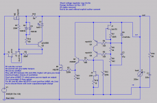
reg-v2n-5m
Bill, here's the next iteration, 5m. Haven't built exactly this version but variations on it. Again, this is for the more advanced diy-er.
I have a new version in the pipeline using a simpler but potentially better CCS. I'm waiting for parts to build that one.
Bill, here's the next iteration, 5m. Haven't built exactly this version but variations on it. Again, this is for the more advanced diy-er.
I have a new version in the pipeline using a simpler but potentially better CCS. I'm waiting for parts to build that one.
Attachments
Last edited:
I was about to cut the boards in a day or so, so it is not too late to change it from 5k to 5m.
I have noticed that you have 220n + 2R at the output replacing the previous 4uF at the output.
Is that for similation only? or does it require now to delete the 4uF and add in the snubber?
I am currently having 4.4uF MKP || 22uF electrolytic at the output plus 4.4uF MKP at the load, without padding resistors, without any oscillation whatsoever.
Last edited:
- Status
- This old topic is closed. If you want to reopen this topic, contact a moderator using the "Report Post" button.
- Home
- Amplifiers
- Power Supplies
- My take on a discrete shunt voltage regulator