To clear up some misunderstandings!
Loudspeakers behave like RL elements and have a high inductive impedance at high frequencies. To effectively dampen any HF oscillations, the RC element R25-C7 is used. R25 is chosen to be approximately as large as the loudspeaker impedance. C7 is calculated as C7 = 1/(2pi*fg*R25). This is achieved by the Zobel element or the Boucherot element.
There are no coils in a Zobel element. A coil resistance
circuit (connected in parallel) is called a Thiel circuit. Makes more sense if you have electrostatic speakers in your system.
Protection of power amplifier and loudspeaker!
One remark first: fuses protect neither the power transistors nor the loudspeakers, as they are much too slow to trip. Nevertheless, fuses are recommended, namely to protect the transformer and to reduce the risk of fire.
Discharge inductive overvoltages!
The loudspeaker is driven by a solenoid coil. Therefore, the impedance has an inductive component. If the current changes rapidly, inductive overvoltages can occur and destroy the transistors. Protection is easily possible with two diodes from the output to the two supply voltages, which discharge any overvoltages to the low-impedance supplies.
A member here complained that the trace at the junction Q5 collector-anode D8 was too thin!
The conductor path is 1mm wide and therefore completely adequate. Especially as the collector current Q5 is <-20mA at full output! To understand, a track with a width of 1mm can deliver a maximum current of approx. 3 Amps at 20°C ambient temperature.
Actually, the transistors Q5 and Q6 (2SC3417) do not need a heat sink. The power dissipation is approx. <600mW and thus still within the green range of the specification.
Thanks again to member STV for the SVG graphic file.
Thank you !
Hi Oscar,To clear up some misunderstandings!
Loudspeakers behave like RL elements and have a high inductive impedance at high frequencies. To effectively dampen any HF oscillations, the RC element R25-C7 is used. R25 is chosen to be approximately as large as the loudspeaker impedance. C7 is calculated as C7 = 1/(2pi*fg*R25). This is achieved by the Zobel element or the Boucherot element.
There are no coils in a Zobel element. A coil resistance
circuit (connected in parallel) is called a Thiel circuit. Makes more sense if you have electrostatic speakers in your system.
Protection of power amplifier and loudspeaker!
One remark first: fuses protect neither the power transistors nor the loudspeakers, as they are much too slow to trip. Nevertheless, fuses are recommended, namely to protect the transformer and to reduce the risk of fire.
Discharge inductive overvoltages!
The loudspeaker is driven by a solenoid coil. Therefore, the impedance has an inductive component. If the current changes rapidly, inductive overvoltages can occur and destroy the transistors. Protection is easily possible with two diodes from the output to the two supply voltages, which discharge any overvoltages to the low-impedance supplies.
A member here complained that the trace at the junction Q5 collector-anode D8 was too thin!
The conductor path is 1mm wide and therefore completely adequate. Especially as the collector current Q5 is <-20mA at full output! To understand, a track with a width of 1mm can deliver a maximum current of approx. 3 Amps at 20°C ambient temperature.
Actually, the transistors Q5 and Q6 (2SC3417) do not need a heat sink. The power dissipation is approx. <600mW and thus still within the green range of the specification.
Thanks again to member STV for the SVG graphic file.
Thank you !
1) First, don’t try and take things out of context - referring to the word complain used by you.
It was a friendly observation period.
2) And understand your point on the Thiel network - I will look into that to better my understanding. Thank you
")
3) The reference of the track is Q10 Collector going to the speaker out terminal ie when the board is seen from the bottom side.
as seen in the below screenshot, Since it looks thinner than the one on the Top layer. - I had put the note via phone so Q10 became Q5 - Apologies.
4) I can't say why but this board seems to have some resemblance with the board by Alex
5) There needs to be a little more room maybe let's say 5mm spacing from the body to body for the VAS transistors as they would need some amount of heatsink can be attached.
6) one more change I could see is that not all will have great soldering skills and some time green masking could be a bit open with economical board makers. so could move this center pad tracks to the top layer so it will not pass between the two pads.
7) Maybe we could move the R18 and C12 down a bit and make the Collector track going to R18 Straight and increase the spacing between the track and pad.
9) it appears it does not need to be a dual-layer layout and it can be easily drafted symmetrically even on a single layer.
there seems to be plenty of space on the board for R18, C12, R7, R5, and R6 to be placed symmetrically and also Q5 and Q6 can be placed such that they can have individual U-shaped heatsinks.
Last edited:
Hello Aditya,
First of all, thank you for your message, the track width of collector Q10 is sufficient. With the Circlo Version with 130W / 4R (V+,V- 35VDC)
and the values given in the chart, the load current of collector Q10 is about (Ieff) 4 amps. With a pure sine wave signal of approx. 1kHz. But I will have another look at it.
Q5,Q6 cooling can be solved easily with an aluminium strip with a size of 25*15*2mm. Please isolate the transistors. More is not necessary. The hole spacing is 10mm.
But it is not necessary, I think it should remain within a reasonable financial framework.
I hope I have helped you for the time being.
Thanks OSGO !
Hey Oscar,Hello Aditya,
First of all, thank you for your message, the track width of collector Q10 is sufficient. With the Circlo Version with 130W / 4R (V+,V- 35VDC)
and the values given in the chart, the load current of collector Q10 is about (Ieff) 4 amps. With a pure sine wave signal of approx. 1kHz. But I will have another look at it.
Q5,Q6 cooling can be solved easily with an aluminium strip with a size of 25*15*2mm. Please isolate the transistors. More is not necessary. The hole spacing is 10mm.
But it is not necessary, I think it should remain within a reasonable financial framework.
I hope I have helped you for the time being.
Thanks OSGO !
Thank you for taking my points in a good spirit, I am learning from you and I am also sharing what I learn and what I do not understand.
In my opinion the output track for Q10 please try and keep it away from the edge of the board for fabrication reasons nothing else.
Hello gannaji,
Did you mean the dimensions of the mounting holes? So the hole spacing?
See picture.
I meant how are you going to mount the power transistors on the heatsink ?
Mr Elvee,
I need your advice:
I intend to build another MOSFET C with a higher power output devices. I have in my mind "N-Channel MOSFET, 120 A, 200 V, 3-Pin TO-247 IXYS IXFH120N20P". Max power dissipation 714W.
However its data sheet does not say it is suitable for audio applications.
Will this device be suitable for linear audio applications and can I use it in a higher power C say 300W RMS. Thanks
Maybe I need some help,
Just read in the Post (#2267)Mosfet transistors with incredible values, and Elvee takes the trouble to answer this.
Can't we just leave this complete and very good power amplifier that Elvee has developed at the values.
Who needs max. 2 * 130W in their house?
If you need more, you can find great amplifiers on the market, but they can't be compared to the Circlophone.
I have designed a preamplifier for the Circlophone and am asking if anyone is interested.
Thanks Osgo !
Please ! Do post it !If you need more, you can find great amplifiers on the market, but they can't be compared to the Circlophone.
I have designed a preamplifier for the Circlophone and am asking if anyone is interested.
Thanks Osgo !
Thanks. Do you have any other alternative in you mind?The DC SOA stops at 50V, which is not sufficient for high power amplifier
Hello,
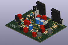
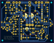
Ok, new try. Made mistake in previous post. forgot the Q7 leader to Q8... Thanks to oscargolf how noted this.
Then I also was not really happy about the placement of the outputs transistors.
See pictures. if someone has some opinion to the layout, please share your thoughts
This will be single side board with 4 jumpers.
I will mill out this board in my PCB mill later on. all tracers is around 1.5 mm
BTW the KiCad 6 files are available
/ Brgds
Attachments
I have another question and I'm too lazy to read through all the
contributions. If I want to use an input potentiometer, is a 20kohm potentiometer too high?
So a volume control?
@Msander68 Your layout looks very good.
contributions. If I want to use an input potentiometer, is a 20kohm potentiometer too high?
So a volume control?
@Msander68 Your layout looks very good.
Nice to see this place live and sound! My circlo is still waiting for me in a little shoe box . I only wanted to share that i had 20 pcs of nxp bc556b from electronics saloon (i think it closed when HK became China again), and also 20 ARROW On semi. I measured HFE with a simple circuit (1mA), and the ON semi measured higher, a gaussian distribution arround 380 vs 340 for the nxp. I dunno if hfe (alternate current) may differ, but the on semi 556b seem more than suitable, maybe i was lucky, but i dont think C rated BC's are needed. Not sure where that came from tho... Its trivial, i was just really happy to see this thread going, and there are even some new pcb's avaiable. I hope one day i will make my Circlo Dream come true ! enjoy!
PS: check page 80 comment 1581: "If a volume pot is placed directly in front of the amplifier, its value should be 4.7K or less."
Terranigma then said that a higher pot may be suitable for the fet version as input impedance is significantly higher.
. I only wanted to share that i had 20 pcs of nxp bc556b from electronics saloon (i think it closed when HK became China again), and also 20 ARROW On semi. I measured HFE with a simple circuit (1mA), and the ON semi measured higher, a gaussian distribution arround 380 vs 340 for the nxp. I dunno if hfe (alternate current) may differ, but the on semi 556b seem more than suitable, maybe i was lucky, but i dont think C rated BC's are needed. Not sure where that came from tho... Its trivial, i was just really happy to see this thread going, and there are even some new pcb's avaiable. I hope one day i will make my Circlo Dream come true ! enjoy!PS: check page 80 comment 1581: "If a volume pot is placed directly in front of the amplifier, its value should be 4.7K or less."
Terranigma then said that a higher pot may be suitable for the fet version as input impedance is significantly higher.
After reading a post - as per @Elvee i thinks it’s mentioned that the pot needs to be below 10k ohm or else the distortion would increase or so. I would suggest pga23xx as output of these device’s is capable of running load of down to 600ohms.I have another question and I'm too lazy to read through all the
contributions. If I want to use an input potentiometer, is a 20kohm potentiometer too high?
So a volume control?
@Msander68 Your layout looks very good
- Home
- Amplifiers
- Solid State
- ♫♪ My little cheap Circlophone© ♫♪