Cool documentation.Hello, it is defensively time for me as well to join the Circlophone community, planing the build with start of getting all components.
Well what to say, this thread is massiveincluding builders thread. anyhow, tried to find some more comprehensive BOM, but all parts are described loosely thru all the posts. So I have tried to do one myself, purchase from Mouser. I'm a fan of open software so the file is Open office, not everybody like to open this kind of files (virus and stuff) so attached PDF as well. With that said, BOM is a BJT version. if someone has any comments i will add or remove. Next to do is trying to fix the PCB in KiCad and use FlatCam for my CNC Router. / Brgds
1) what output power do you want.
2) Value of Load
3) preferably stay with 4MHz devices
(MJL21194) on output. You would need
a miller cap else and a oscilloscope to
check for high frequency oscillation (
heat ).
4) as per Katiyar He suggests 3503 for
VAS as the VAS need to have COB
below a value. 2N3019 are a little
expensive.
5) Important R21 and zener diode will be
decided by your operating voltage as
mentioned in drawing. Just saying.
6) there is a post in the builders thread regarding output driver and sound quality either by Elvee or Daniel.
For my build I have taken COG /NPo for all the caps except the input one, I have a Muse 4.7 bipolar.
And drivers are BD140 and Power Transistors are MJL21194
amd resistors are a mix what’re I could find with lower PPM with respect to cost
And keep heat sinks for VAS transistors they will get HOT.
These are just my thoughts. I am not going above 25 - 30 watts in 8ohms
also better look for a heat sink with 0.5c/w or lower.
Good For you - NanoFarad # Bhowmick
What are you trying to say? Be specific.i have no complex................. i think you have after seeing some replies you have given on this forum. and it was not a very decent way to say something to some one who may not know a lot of things.
Are you moderator of this forum? If no then leave it to them. Who are you to judge me?!
If you don't know Sanyo made some excellent transistors for voltage amplification stage (Primarily for HI-End CRT tvs), like 2sc3955 (Ft-300Mhz typ).
At 20ma the unity gain bandwidth of c3417 is beyond 70Mhz! Cob- 2.6pf typical. Which is very good for VAS. So that part is not only good for me but desirable for many! OTOH the beauty of Circlophone is it doesn't require such hard to find parts & has all the goodies of Class-A.
Anyway we are here to discuss & to help each other. I don't have an EE degree & completely newbie as well. If you don't have anything to contribute then don't pollute this wonderful thread by your gibberish. thank you, have a nice day.


If it wants 10 pF, it will work better and have lower high frequency distortion if your transistor has 2.6 pF and you add 6.8 or 8.2 pF polystyrene, COG or mica in parallel than if your transistor had 10 pF. Lower Cob = better VAS. You just have to get to the right value, somehow.
hey thank you for the catch, ( my dyslexia ) But i correct my self and have bought 2N3019, about 45/- each. was looking for KSC3503 but didnt find it.
Replaying to post #2147 and #2243 second & third para(see above).
Then why you were looking for c3503(Cob-2.6 typical)?! Just because Mr.katiyar recommended that? Katiyar knows what he is doing, you do not.Certainly Not good for you!
I never mocked him just because he is using venerable 2n3055/3773 as outputs but i believed him(probably a newer, 3Mhz part) & soon going to have such to3 for my Class-A experiments. The thing is for DIY we always use what is available to us, nothing wrong in that. But who doesn't like to go extreme?
Anyway i have very good temper & that's why i do not want to drag this issue anymore. Just choose your word wisely!
Last edited:
Mr Msander68,
Welcome to Me Elvee's Circlophone Forum.
I saw your BOM for Circlophone. The original choice for VAS is 2N3019 which is now hard to find but as per your BOM it is available at Mouser. This transister is ideally suitable for a Rail voltage of +-25V DC. If you need to increase the rail voltage further to get higher power, you need to change the specs of all transistors in order to sustain higher voltage.
I tested 2SC 2621 Sanyo Japan (Pulled from my discarded CRT colour TV (4.7 pf added between B&C), BF869 (original Philips spares bought in 1985) and KSC3503 in my BJT Circlophone prototype version. All transistors worked very well.
The cost of 2N3019 seem very high. My advise would be to use KSC3503 in VAS which is still under production by ON Semiconductor and is available at almost one third price as per Mouser website.
I am using KSA1381 in VAS in my MOSFET version of Circlophone which is complimentry to KSC3503.
Replaying to post #2240
@Msander68 Hi, i've seen your BOM. If you want to build a low power version of Circlo then my recommendation would be BC556C (KSA992) for input pairs, BC546B (KSC1845, 2N5551) for Q12 & Q13, BD140 (KSA1837/MJE15029) for drivers. For outputs TIP35C, MJL21194 (MJ21194). For Q5-Q6 KSC3503 is a very good choice, i'll use C3417 there because i've lot of them. For D4 & D5 3A to 5A SR350,SR5100 (MBR1035) type schottky is fine. For capacitors in pf range NPO/COG ceramics are excellent, no need to use big & expensive polypropylenes so you can design a compact PCB. Wish you good luck.
Last edited:
Dear Community, Mr. Elvee,
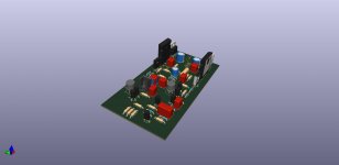
Well, this thread is massive, phhh. Couldn't find any KiCad files available... so I made it myself. Attached another PCB done to death. The PCB is designed for milling. With 0.4mm V-Bit. The 3D file is supposed to have the BJT underneath of the PCB to the heat sink and PCB on top. I like PCB to be more rectangular and not so wide.
BUT I think I made a mistake or not? Well, why not go with the Zenerless Circlophone.
There is several examples, especially Post #579/1905 and in particular 1743 As-Built by minek123
So small question, post 579 containing two examples witch is better or some-same. left example or right example?
Post 1743. Mr. minek123, have replaced the D8 and D9 with Q14. any toughs about this or should i just go with original as post 1.
is there any benefits with CCS and no Zener. the voltage will probably not fluctuate at all. will use active power supply by Tibi in this forum.
BTW, just to mention, I will of course share all KiCad files. but this is just rev A . need to fiddle around somewhat. if you need now-now just PM me. but it is Rev A / Brgds / Mikael
Well, this thread is massive, phhh. Couldn't find any KiCad files available... so I made it myself. Attached another PCB done to death. The PCB is designed for milling. With 0.4mm V-Bit. The 3D file is supposed to have the BJT underneath of the PCB to the heat sink and PCB on top. I like PCB to be more rectangular and not so wide.
BUT I think I made a mistake or not? Well, why not go with the Zenerless Circlophone.
There is several examples, especially Post #579/1905 and in particular 1743 As-Built by minek123
So small question, post 579 containing two examples witch is better or some-same. left example or right example?
Post 1743. Mr. minek123, have replaced the D8 and D9 with Q14. any toughs about this or should i just go with original as post 1.
is there any benefits with CCS and no Zener. the voltage will probably not fluctuate at all. will use active power supply by Tibi in this forum.
BTW, just to mention, I will of course share all KiCad files. but this is just rev A
. need to fiddle around somewhat. if you need now-now just PM me. but it is Rev A / Brgds / MikaelAttachments
CCS proposed by Elvee, and used by Terranigma is better than the one I used (according to Elvee's simulations in post #579).
The primary benefit of using CCS is that you can use different rail voltages without changing Zeners.
So if you not sure what PSU voltage you will be using, it's better to go with CCS.
The primary benefit of using CCS is that you can use different rail voltages without changing Zeners.
So if you not sure what PSU voltage you will be using, it's better to go with CCS.
here is a photo. surprisingly nice quality. Although pcb is single sided , they used soldermask on both sides.
PCB power: good quality pcbs but costly.
It would be nice if the input pair Q3 & Q4 were facing each other instead of back to back.
So that we could use the HFE matched pairs fused to each other to main equilibrium.
hello @oscargolf , great looking PCB!a new version of Circlophone PCB
let me know if you would like the modified "gronenbourg" logo (similar to elvee's avatar).
I made a vector graphic version of it and can export any file format (SVG, EPS, PDF, DXF ... )

shouldn't be a deal breaker. you may do it like belowIt would be nice if the input pair Q3 & Q4 were facing each other instead of back to back.
So that we could use the HFE matched pairs fused to each other to main equilibrium.
https://www.diyaudio.com/community/threads/my-little-cheap-circlophone-c.189599/post-2876598
flip c--e and isolate legs with insulation.
or check dc offset stability .
Last edited:
I feel the board could be smaller or we could add the below points with the same size board.
also the output track could be artistic like the rest of the of the board. Sorry 😞 I don’t mean to sound a broken record. Nor make enemies.
Just some thoughts from a lazy guy
1) add 20*5mm fuse holder
2) give little more space for heat sinks on2N3019 replacement transistors
3) make space to keep the zobel on board and the inductor vertical mounted to save space.
4) may be also bring the protection board
on it.
5) Q5 Collector track going to the output could be a bit larger and away from the border
Last edited:
That is also do-able but If I was going for a bread board I would do that.shouldn't be a deal breaker. you may do it like below
https://www.diyaudio.com/community/threads/my-little-cheap-circlophone-c.189599/post-2876598
flip c--e and isolate legs with insulation.
or check dc offset stability .
Why smaller than 100mm x 68mm?I feel the board could be smaller or we could add the below points with the same size board.
also the output track could be artistic like the rest of the of the board. Sorry 😞 I don’t mean to sound a broken record. Nor make enemies.
Just some thoughts from a lazy guy
1) add 20*5mm fuse holder
2) give little more space for heat sinks on2N3019 replacement transistors
3) make space to keep the zobel on board and the inductor vertical mounted to save space.
4) may be also bring the protection board
on it.
5) Q5 Collector track going to the output could be a bit larger and away from the border
Sorry my bad - I read 86. ( I am dyslexic).Why smaller than 100mm x 68mm?
Thank you for updating 😊
- Home
- Amplifiers
- Solid State
- ♫♪ My little cheap Circlophone© ♫♪