Elvee, as you might know member peufeu started a thread about amplifier output topology comparison. At this post he bashed quasi complementary topology very badly.
I wonder that how his experiments related with Circlophone's quasi output stage (for both MOS and BJT). I know that Circlophone is a different topology that relies on auto bias mechanism but since it uses same sex output devices, does it behave similar on some aspects that peufeu exhibited? Thanks.
I wonder that how his experiments related with Circlophone's quasi output stage (for both MOS and BJT). I know that Circlophone is a different topology that relies on auto bias mechanism but since it uses same sex output devices, does it behave similar on some aspects that peufeu exhibited? Thanks.
I know Circlophone is not text-book quasi but I think that there is a possibility of that sharing some similar behavior with text-book quasi due to the non complementary output design. This is the main motivation behind my question.Circlophone is not quasi.
No trace of quasi design here - look at Pass/Firstwatt F6 (easier insight)....sharing some similar behavior with text-book quasi due to the non complementary output design....
You got two same-sex devices at the output but driven with signal in opposite phase - hence the "Circlo" part of the name (circlotron uses the same trick)
I will share photographs of pcb once they are here.
regards
prasi
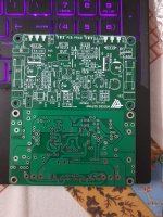
here is a photo. surprisingly nice quality. Although pcb is single sided , they used soldermask on both sides.
PCB power: good quality pcbs but costly.
Attachments
")
You got two same-sex devices at the output but driven with signal in opposite phase - hence the "Circlo" part of the name (circlotron uses the same trick)
Thanks. Wish I asked this much before. Being too late is no worse than never.
here is a photo. surprisingly nice quality. Although pcb is single sided , they used soldermask on both sides.
Nice looking PCBs. I thought you used both layers but it seems not.
Exactly.No trace of quasi design here - look at Pass/Firstwatt F6 (easier insight).
You got two same-sex devices at the output but driven with signal in opposite phase - hence the "Circlo" part of the name (circlotron uses the same trick)
However it does use CFP's (although it is not required: the circuit also works with darlingtons for example, with a slightly reduced output swing), but the CFP's never turn-off, and are permanently under the control of the circlo servo engine.

Elvee, as you might know member peufeu started a thread about amplifier output topology comparison. At this post he bashed quasi complementary topology very badly.
I wonder that how his experiments related with Circlophone's quasi output stage (for both MOS and BJT). I know that Circlophone is a different topology that relies on auto bias mechanism but since it uses same sex output devices, does it behave similar on some aspects that peufeu exhibited? Thanks.
Circlo is completely different from quasi complimentary.
In a "normal" push pull with opposite polarity devices, the sum of the voltages across the Vbe junctions of the power transistors and associated emitter resistors is held constant because it is generated by a Vbe multiplier.
In the circlo the same voltage is held constant because it comes from both collector currents of a differential pair. But it works in the same way.
In fact Circlo works quite like a normal push pull except one half is upside down.
The important thing isn't the polarity of the devices, but how they are controlled.
In the quasicomp both devices are controlled in completely different ways, one is a darlington and the other is a CFP, they only look symmetrical but they are not, and the crossover is a mess. On the other hand the circlo has two identical halves controlled in the same way from the outputs of a differential pair, so it should have very good symmetry.
Also the CFPs in the circlo don't work in the same way as in a CFP output stage.
Last edited:
Mr Elvee,
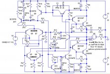
I have a question in my mind which you can answer as a designer of Circlophone . Can we replace Zener diodes with some other device to maintain constant voltage as I think zener is a noisy device? Also value of zener is to be changed with respect to Rail voltage.
Thanks
I have a question in my mind which you can answer as a designer of Circlophone . Can we replace Zener diodes with some other device to maintain constant voltage as I think zener is a noisy device? Also value of zener is to be changed with respect to Rail voltage.
Thanks
Mr Elvee,
I have a question in my mind which you can answer as a designer of Circlophone . Can we replace Zener diodes with some other device to maintain constant voltage as I think zener is a noisy device? Also value of zener is to be changed with respect to Rail voltage.
Thanks
I suggest you to read from post #572 to the post #578. There is a "cascode" solution for this which requires an extra transistor with same power dissipation factor of Q5,Q6.
@peufeu, Thank you for excellent brief info.
Mr Terranigma,
I did not get success in replacing the Zeners with the transistor. No amplification and R7 started heating up. By touching input it starts oscillating like amplification for a moment and then a typital silence and again same phenomenon. But in your simulation it worked.
I want to mention here that my rail voltage for experiment was 18-0-18V DC. May be a minimum voltage is required to function it effectively. Could you please throw some light on this.
Thanks
Attachments
Katiyar,
I built a circlophone with transistor in place of zeners.
see post #1743
Everything worked fine. I don't think there is 'minimum voltage' preventing replacing Zeners with transistor.
I built a circlophone with transistor in place of zeners.
see post #1743
Everything worked fine. I don't think there is 'minimum voltage' preventing replacing Zeners with transistor.
Mr Terranigma,
I did not get success in replacing the Zeners with the transistor. No amplification and R7 started heating up. By touching input it starts oscillating like amplification for a moment and then a typital silence and again same phenomenon. But in your simulation it worked.
I want to mention here that my rail voltage for experiment was 18-0-18V DC. May be a minimum voltage is required to function it effectively. Could you please throw some light on this.
Thanks
Compensation network's placement is different in your schematic. Take a look at 270R + 820pf in Elvee's schematic. It is at post #572.
- Home
- Amplifiers
- Solid State
- ♫♪ My little cheap Circlophone© ♫♪