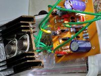
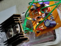
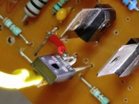
>Compensation network's placement is different in your schematic.
Right, in my schematic in post #1743 it's placed correctly.
Good catch!
But I didn't catch that you actually built a "posh" version of Circlophone. If you have a plan about a beefy MOS version, you may take a look at Alpha & Omega Semiconductor's AOK29S50. There are also smaller ones in TO220 package. AOT9N40, AOT12N30, AOT4S60 and many more.
AOK29S50 has little bit over 1nF input capacitance. That's much better than IRFPs.
Also, according to SOA chart, acceptable current for 50V rails is 4 Amps, which is also not bad....
Perhaps honest 100W (maybe 150W ?) amp can be made with just one pair?
The problem will be cooling. I don't think one TO-247 device can dissipate that much heat. For a real 100W of power, 2 pairs seem like a must, regardless of their ratings..
Edit: Digikey sells them for $4 (not in stock right now, but current).
Edit2: Actually, for 50V rails we need to have devices with 100Vds, which will lower the max SOA amps from 4 to 3, or even less...
Last edited:
Exactly.The important thing isn't the polarity of the devices, but how they are controlled.
In the quasicomp both devices are controlled in completely different ways, one is a darlington and the other is a CFP, they only look symmetrical but they are not, and the crossover is a mess. On the other hand the circlo has two identical halves controlled in the same way from the outputs of a differential pair, so it should have very good symmetry.
Also the CFPs in the circlo don't work in the same way as in a CFP output stage.
In the basic Circlophone, there is a difference in the conditions seen by the drivers, and in principle it could damage the symetry, and the symetry can be restored by using a cascode, but in practice it doesn't seem to make a difference.
In fact, with the cascode, the performances are insignificantly worse, probably because the added non-linearity compensated for something else.
The idea is to drop the voltage, to reduce/equalize the dissipation in the VAS, and any other device having the same result would also work. A varistor would also work.Mr Elvee,
I have a question in my mind which you can answer as a designer of Circlophone . Can we replace Zener diodes with some other device to maintain constant voltage as I think zener is a noisy device? Also value of zener is to be changed with respect to Rail voltage.
Thanks
The noise in that location is practically irrelevant: even a pathologically noisy device couldn't intrude in the output signal, thus feel free to use anything you prefer. Zeners are cheap, easily available in any voltage making them an ideal choice
Mr Terranigma,
I did not get success in replacing the Zeners with the transistor. No amplification and R7 started heating up. By touching input it starts oscillating like amplification for a moment and then a typital silence and again same phenomenon. But in your simulation it worked.
I want to mention here that my rail voltage for experiment was 18-0-18V DC. May be a minimum voltage is required to function it effectively. Could you please throw some light on this.
Thanks
Terra has correctly spotted the issue: the compensation is made ineffective, causing oscillations.Compensation network's placement is different in your schematic. Take a look at 270R + 820pf in Elvee's schematic. It is at post #572.
Why is R7 in particular heating up is a mystery: there might be another issue hidden somewhere
Sensible advice: for domestic use, you could probably get away with a single pair, but for more serious uses, 2 pairs or more are unavoidableAOK29S50 has little bit over 1nF input capacitance. That's much better than IRFPs.
Also, according to SOA chart, acceptable current for 50V rails is 4 Amps, which is also not bad....
Perhaps honest 100W (maybe 150W ?) amp can be made with just one pair?
The problem will be cooling. I don't think one TO-247 device can dissipate that much heat. For a real 100W of power, 2 pairs seem like a must, regardless of their ratings..
Edit: Digikey sells them for $4 (not in stock right now, but current).
Edit2: Actually, for 50V rails we need to have devices with 100Vds, which will lower the max SOA amps from 4 to 3, or even less...
Sensible advice: for domestic use, you could probably get away with a single pair, but for more serious uses, 2 pairs or more are unavoidable
Elvee, you sound like that it is possible to add more pairs to output. As far as I know, your investigation on building a high-power version of Circlohone didn't end up well. Have you any estimation of that it can be done with MOSFETs without much hassle?
PS: I see that Minek asking similar question.
I actually forget to change the compensation network 270R + 820pf on the pcb layout. You draw my attention towards my mistake. After changing compensation network, the amplifier started working but with distorted sound. I therefore put 270pf capacitor between base and collector of the transistor as a trial which eventually corrected the distortion. With this transistor circuit I am getting distortion free sound over wide range of rail voltage.
Thanks
Thanks
After changing compensation network, the amplifier started working but with distorted sound. I therefore put 270pf capacitor between base and collector of the transistor as a trial which eventually corrected the distortion.
Nice to hear that but no one complained about a distorted sound after implementing the cascode, including myself. Did you check your circuit with zener? is it healthy with zeners?
With matched MOSfets, it is most probably possible, without the source resistors.Elvee, would this be workable with current circlophone design:
1) use 2 pairs of mosfets (matched)
2) with 0.22 Ohm source resistors
3) rails 50V to 60V
?
Matching is essential for Fets, due to the large threshold voltage dispersion.
Once the matching is OK, the resistors can be dispensed with, since the equivalent intrinsic source resistance is higher than for BJT's (and Peufeu's excellent work showed that thermal stability of vertical FETs is not as bad as commonly believed).
50-60V rails shouldn't be problematic per se, but the circlo engine may have troubles due to the Early effect.
When I studied the possibility of a higher power C, this was one of the problematic issues.
However, modern transistors vastly outperform their historic spice models, and in reality it might be a non-issue.
Only a real-world test can decide whether this conjecture is valid or not.
As I said above, paralleling MOSFets is much less problematic than BJT's, and if you parallel devices for high power, low-Z operation, 2 ohm or 1 ohm, I do not foresee any problem.Elvee, you sound like that it is possible to add more pairs to output. As far as I know, your investigation on building a high-power version of Circlohone didn't end up well. Have you any estimation of that it can be done with MOSFETs without much hassle?
PS: I see that Minek asking similar question.
For a more conventional 8ohm, it has to be checked in reality, because the higher voltage could become problematic with the servo transistors.
Matching is essential for Fets, due to the large threshold voltage dispersion.
Sorry for asking but we need at least 4 devices of same type. Should all of them to be matched or is 2 + 2 matching going to be ok?
and Peufeu's excellent work showed that thermal stability of vertical FETs is not as bad as commonly believed
It depends on the model though
IRFP240/9240 have pretty civilized tempco ; the FQP FETs are another story, much higher tempco... so if someone tries another brand, who knows what you will get!
Still worth trying, of course.
Mr Elvee, The circlophone is working perfectly with Zeners but by cascode transistor arrangement it is giving me noticable distorted sound which could be corrected only by putting 270pf cabacitor between BC as a trial.
Other boarders succeeded with cascode arrangement without this compensation capacitors as also evident in their simulation. I could not trace out the fault. If at all a compensation capacitor is required in this arrangement what could be the lowest value so that it does not effect High frequencies, stability and distortion.
Could it be due to the transistors used by me in VAS and cascode which are Video transistors pulled Sanyo C2621 I used. I have now noticed that the voltage across the base of driver transistors is exactly same as rail voltage. I tried with 18-0-18 and 33-0-33 V rail voltage and found no change in sound clarity which is excellent.
Please help.
Questions to versions
Hi,
I get a litte bit lost in this thread.
I know there are the standart schematic with
- BJT Outputs
and versions with
- Mosfet outputs (IRFP240).
Now my questions:
Regards Chris
Hi,
I get a litte bit lost in this thread.
I know there are the standart schematic with
- BJT Outputs
and versions with
- Mosfet outputs (IRFP240).
Now my questions:
- What ist the max. SupplyVoltage for both versions?
- What Output power can be achived with both versions?
- What is the best working schematic for the Mosfet Version of the Circlophone?
Regards Chris
"Official" proposed max rails are +-50V according to early posts of Elvee. I think that this doesn't mean that you can't experiment higher voltages with modern parts (especially for Q5,Q6 servo transistors). I'm using 45V rails with 2SA1370's as servo, IRFP240's as outputs.[*]What ist the max. SupplyVoltage for both versions?
post #72[*]What Output power can be achived with both versions?
[*]What is the best working schematic for the Mosfet Version of the Circlophone?
You have to read post #56 first in order to understand the component selection.
First proposet MOS version is at post post #62 and post #64.
My version (without VAS compensation network) on daily usage is here. 65V rails on that schematic is for simulation. In that schematic, I use Elvee's CCS circuit instead of R21. If you follow original schematic R21 chart is at post #1864.
Thanks Terra for answering to Ampi.
A useful tip if you need practical info about the Circlophone, like dimensioning, devices, supply voltages, etc: first have a look at the builder's thread opened by Daniel:
Building Elvee's Circlophone: Documentation, Parts, Accessories, & beginner friendly
Chances are you will find an answer there for all recurrent questions
- Home
- Amplifiers
- Solid State
- ♫♪ My little cheap Circlophone© ♫♪


