I haven't registered, trade-marked or patented any part of the design, description or name, meaning I only enjoy the default protection afforded to any intellectual work or creation (for example, even a simple letter you sent to a friend remains your IP, and cannot be published without your agreement).Is "Circlophone©" a copyrighted design? Have you any patent for its design principles? I'm asking this for curiosity. In what conditions you'll permit that it becomes a commercial product? I guess producers might have to contact with you for settling on a legal agreement.
I could in theory object to the use and reproduction of the schematic, name, logo, etc, but I cannot prevent anyone from using part or totality of the principles in another amplifier: I would need patents for that.
Anyway, I have put the C in the public domain from the start, and anyone is free to use parts or totality of the design the way he/she likes, to modify it to his/her taste, etc.
You can even use it in a commercial project, and make money from it.
Kits vendors have asked me for the permission, and I granted them. They proposed a financial compensation, but I refused: the project is free for all to use, you do not even have to ask for my permission.
What you cannot do is appropriate the design, for example by patenting it (it would be difficult anyway, because the prior art is glaringly obvious), or claiming it as your IP.
It has to remain free for all. If you make money with it, good for you, you deserve it.
For example, a 2N5401 from Nexperia can dissipate 630mW @25°C amb, so it should be good for up to 300mWAttached. If - as Elvee suggested - that TO-92 transistors are good for at least 150mW, than all the transistors in this schematic should work fine.
No need for TO-126.
I haven't registered, trade-marked or patented any part of the design, description or name, meaning I only enjoy the default protection afforded to any intellectual work or creation (for example, even a simple letter you sent to a friend remains your IP, and cannot be published without your agreement).
I could in theory object to the use and reproduction of the schematic, name, logo, etc, but I cannot prevent anyone from using part or totality of the principles in another amplifier: I would need patents for that.
Anyway, I have put the C in the public domain from the start, and anyone is free to use parts or totality of the design the way he/she likes, to modify it to his/her taste, etc.
You can even use it in a commercial project, and make money from it.
Kits vendors have asked me for the permission, and I granted them. They proposed a financial compensation, but I refused: the project is free for all to use, you do not even have to ask for my permission.
What you cannot do is appropriate the design, for example by patenting it (it would be difficult anyway, because the prior art is glaringly obvious), or claiming it as your IP.
It has to remain free for all. If you make money with it, good for you, you deserve it.
What else to say.. thank you again for such kind motivation.
I'm an IT person and making a living by the cumulative efforts of the Open Source Software community whom formed by the great people all around the world. I think that you rely on same purpose: doing something good and useful for other people in need without any financial gain. There are a lot things to say about this but I like to make it short and simple: Thank you.
That's very nice of you, Elvee. Not that I plan to profit from the circlophone, but I think your approach represents very nicely the spirit of DIY, as opposed to the behavior of some other participants of this forum, who are guarding 'their' designs, .asc files, gerbers, etc.. like they were expecting to get Nobel award for it ")
I personally feel that commercial production of any DIY design should be prohibited as the interest and the efforts put by the designer is enormous and people should not make money by producing it commercially. Any design on this forum should be used for personal use only.
I personally feel that commercial production of any DIY design should be prohibited as the interest and the efforts put by the designer is enormous and people should not make money by producing it commercially. Any design on this forum should be used for personal use only.
I just want to notice that I don't feel comfortable with such idea. There are people around who just want to listen good music without any skillset of electronics. If someone decides to make Circlophone available for such people for a reasonable profit, I just can't find a reasonable cause for condemning such business except ethical stand point like deceptive information, bad quality etc.
There is an inverted fet version by member @Piersma. It is not fully FET version as you can see that it uses PNP BJT's as output devices. Maybe someone could modify it for a complete jfet + MOS version. You can search in thread or just follow the link below:Is that any fet version for this amplifier?
Inverted J-FET Circlophone Builders thread
Last edited:
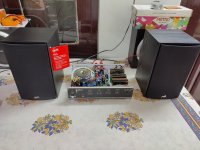
Finally assembled two MOSFET boards in a salvaged enclosure. The circuit and layout has now been tested fully and I finally connected Polk T15 speakers to feel the audio quality. It is simply excellent. The only constraint could be heat issue at higher power due to small enclosure size.
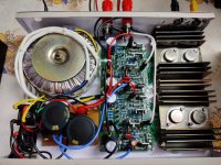
Following main components used in the build;
MOSFET - IRF350 (as I already had with me)
VAS - ON KSA1381 (Original from RS)
BC546B & MPSA 42 - ON (Original from RS)
2N5401 - KSA original
BAT54 - SMD placed under board (Original from RS)
MBR745 - Taiwan Semiconductors (Original from RS)
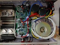
I have made some changes in CCS circuit after various iterations done on LT Spice and found that the present circuit maintains constant current over wide range of voltage from 18V to 65V DC. The variation in current is ~ 2ma during this range. CCS transistor is MPSA 42. The present layout accomodates CCS circuit. At current supply voltage MPSA 42 does not heat up but not sure at higher voltages.
I have not used Cascode transistor as I found it not very suitable for lower voltages so I revert back to 16+16V Zeners.
The measurements are as follows which are very near to simulation except for offset
Supply Voltage - 35-0-35V DC
Offset Voltage (-3.5V- 4V) & (-5V - 6V)
Quisent Current (154ma & 160ma).
HEXFET.asc file on which simulation has been done is also enclosed.
High resolution print of top and bottom layer of PCB is attached.
Following main components used in the build;
MOSFET - IRF350 (as I already had with me)
VAS - ON KSA1381 (Original from RS)
BC546B & MPSA 42 - ON (Original from RS)
2N5401 - KSA original
BAT54 - SMD placed under board (Original from RS)
MBR745 - Taiwan Semiconductors (Original from RS)
I have made some changes in CCS circuit after various iterations done on LT Spice and found that the present circuit maintains constant current over wide range of voltage from 18V to 65V DC. The variation in current is ~ 2ma during this range. CCS transistor is MPSA 42. The present layout accomodates CCS circuit. At current supply voltage MPSA 42 does not heat up but not sure at higher voltages.
I have not used Cascode transistor as I found it not very suitable for lower voltages so I revert back to 16+16V Zeners.
The measurements are as follows which are very near to simulation except for offset
Supply Voltage - 35-0-35V DC
Offset Voltage (-3.5V- 4V) & (-5V - 6V)
Quisent Current (154ma & 160ma).
HEXFET.asc file on which simulation has been done is also enclosed.
High resolution print of top and bottom layer of PCB is attached.
Attachments
Anything +/- 50mV is OK.
With transistor LTP (as compared to op-amp) it's never gonna get better than a few mV.
Even if you make it 0mV by same miracle, it's not gonna be stable enough to keep this 0 for long
>KSA1381 are video transistors having Cob of 3.1pf.
You are right. They are good.
With transistor LTP (as compared to op-amp) it's never gonna get better than a few mV.
Even if you make it 0mV by same miracle, it's not gonna be stable enough to keep this 0 for long
>KSA1381 are video transistors having Cob of 3.1pf.
You are right. They are good.
Finally assembled two MOSFET boards in a salvaged enclosure. The circuit and layout has now been tested fully and I finally connected Polk T15 speakers to feel the audio quality. It is simply excellent. The only constraint could be heat issue at higher power due to small enclosure size.
Congrats! Very nice compact build. Did you do any load test in order to observe the heat dissipation with those heatsinks at extent levels? Mounting them vertically could help a little but case dimensions doesn't seem to allow that. If you feel discomfort with the heat at prolonged sessions, you can attach a single 12V computer fan that runs at 5-6V.
Thanks for sharing PCB files.
EDIT: Don't you use any kind of thermal paste between mica insulators and mosfets/heatsink?
Also, I remember KSA1381 were mentioned as having Cob little bit to high for the circlophone...
I think it is very good choice for bias servo. Datasheet specifies it is as 3.1 pF / 150 MHz . Very similar specs with 2SA1370 which is my preference.
Last edited:
Thanks Mr minek123 and Mr terranigma for your advice. I know this build might not sustain full load test as per present setup not due to circuitry but due to limitation of heat sink and size of enclosure. But I had no choice. I have connected this build to my PC output giving me excellent response at room listening levels much much better performance than run of the mill market available amplifiers.
And more so the joy and satisfaction of DIY experience.
Thanks
And more so the joy and satisfaction of DIY experience.
Thanks
I haven't registered, trade-marked or patented any part of the design, description or name, meaning I only enjoy the default protection afforded to any intellectual work or creation (for example, even a simple letter you sent to a friend remains your IP, and cannot be published without your agreement).
I could in theory object to the use and reproduction of the schematic, name, logo, etc, but I cannot prevent anyone from using part or totality of the principles in another amplifier: I would need patents for that.
Anyway, I have put the C in the public domain from the start, and anyone is free to use parts or totality of the design the way he/she likes, to modify it to his/her taste, etc.
You can even use it in a commercial project, and make money from it.
Kits vendors have asked me for the permission, and I granted them. They proposed a financial compensation, but I refused: the project is free for all to use, you do not even have to ask for my permission.
What you cannot do is appropriate the design, for example by patenting it (it would be difficult anyway, because the prior art is glaringly obvious), or claiming it as your IP.
It has to remain free for all. If you make money with it, good for you, you deserve it.
For example, a 2N5401 from Nexperia can dissipate 630mW @25°C amb, so it should be good for up to 300mW
Mr, Prohodimez. Since I did not have foot print of MPSA92 I could not do simulation in LTspice.
I think it will not be a suitable replacement for 2N5401 specially in a circuit where high gain transistor is required. The bottleneck could be low Hfe of MPSA92.
However its counter part MPSA42 worked very well in CCS circuit probably better than other high voltage transistors.
I think it will not be a suitable replacement for 2N5401 specially in a circuit where high gain transistor is required. The bottleneck could be low Hfe of MPSA92.
However its counter part MPSA42 worked very well in CCS circuit probably better than other high voltage transistors.
You can find models of the MPSA92, see this example from Central:
*******
* Spice Model
* Item: MPSA92
* Date: 8/25/10
* Revision History: A
* ==========================================================
* This model was developed by:
* Central Semiconductor Corp.
* 145 Adams Avenue
* Hauppauge, NY 11788
*
* These models are subject to change without notice.
* Users may not directly or indirectly re-sell or
* re-distribute this model. This model may not
* be modified, or altered without the consent of Central Semiconductor Corp.
*
* For more information on this model contact
* Central Semiconductor Corp. at:
* (631) 435-1110 or Engineering@centralsemi.com
* Central Semiconductor Corp. | Home
* ==========================================================
*******
*SRC=MPSA92;MPSA92;BJTs PNP; Si; 300V 0.500A 50.0MHz CS
.MODEL MPSA92 PNP (
+ IS=28.39F
+ BF=127.12
+ VAF=13.033
+ IKF=.1566
+ ISE=103.89E-15
+ NE=1.2763
+ BR=499.50
+ VAR=50
+ IKR=3.5m
+ ISC=1500P
+ NC=2.9970
+ NR=1
+ NF=1
+ RB=11.300
+ RC=778.1m
+ RE=490.00E-6
+ CJE=109.36E-12
+ VJE=1.2027
+ MJE=.36517
+ CJC=22.069E-12
+ VJC=1.5000
+ MJC=.47644
+ TF=5.0525E-9
+ XTF=4.4954
+ XTB=1.5
+ VTF=24.240
+ ITF=.30881
+ TR=4.8693E-6 )
**********
Or Fairchild:
PNP (Is=218.9f Xti=3 Eg=1.11 Vaf=100 Bf=99 Ne=1.307 Ise=218.9f Ikf=.2016 Xtb=1.5 Br=24.67 Nc=2 Isc=0
Ikr=0 Rc=7 Cjc=19.88p Mjc=.4876 Vjc=.75 Fc=.5 Cje=81.49p Mje=.3493 Vje=.75 Tr=516.9p Tf=1.395n Itf=1.5
Vtf=22 Xtf=270 Rb=10
Or Siemens:
.MODEL MPSA92 PNP(IS=9.53E-14 ISE=8.37E-13 ISC=9.99E-11 XTI=3.00 BF=9.80E1 BR=4.78 IKF=3.49E-2 IKR=1.00 XTB=1.5 VAF=2.60E2 VAR=1.40E2 VJE=3.00E-1 VJC=3.00E-1 RE=1.00E-2 RC=1.00E-2 RB=2.76E1 RBM=6.66E-2 IRB=7.02E-4 CJE=9.54E-11 CJC=4.66E-11 .00 FC=5.00E-1 NF=1.00 NR=1.55 NE=1.49 NC=1.50 MJE=4.26E-1 MJC=7.00E-1 TF=9.52E-10 TR=516.9p ITF=4.12E-1 VTF=9.99E5 XTF=1.03 EG=1.11 VCEO=300 ICRATING=500m MFG=SIEMENS)
*******
* Spice Model
* Item: MPSA92
* Date: 8/25/10
* Revision History: A
* ==========================================================
* This model was developed by:
* Central Semiconductor Corp.
* 145 Adams Avenue
* Hauppauge, NY 11788
*
* These models are subject to change without notice.
* Users may not directly or indirectly re-sell or
* re-distribute this model. This model may not
* be modified, or altered without the consent of Central Semiconductor Corp.
*
* For more information on this model contact
* Central Semiconductor Corp. at:
* (631) 435-1110 or Engineering@centralsemi.com
* Central Semiconductor Corp. | Home
* ==========================================================
*******
*SRC=MPSA92;MPSA92;BJTs PNP; Si; 300V 0.500A 50.0MHz CS
.MODEL MPSA92 PNP (
+ IS=28.39F
+ BF=127.12
+ VAF=13.033
+ IKF=.1566
+ ISE=103.89E-15
+ NE=1.2763
+ BR=499.50
+ VAR=50
+ IKR=3.5m
+ ISC=1500P
+ NC=2.9970
+ NR=1
+ NF=1
+ RB=11.300
+ RC=778.1m
+ RE=490.00E-6
+ CJE=109.36E-12
+ VJE=1.2027
+ MJE=.36517
+ CJC=22.069E-12
+ VJC=1.5000
+ MJC=.47644
+ TF=5.0525E-9
+ XTF=4.4954
+ XTB=1.5
+ VTF=24.240
+ ITF=.30881
+ TR=4.8693E-6 )
**********
Or Fairchild:
PNP (Is=218.9f Xti=3 Eg=1.11 Vaf=100 Bf=99 Ne=1.307 Ise=218.9f Ikf=.2016 Xtb=1.5 Br=24.67 Nc=2 Isc=0
Ikr=0 Rc=7 Cjc=19.88p Mjc=.4876 Vjc=.75 Fc=.5 Cje=81.49p Mje=.3493 Vje=.75 Tr=516.9p Tf=1.395n Itf=1.5
Vtf=22 Xtf=270 Rb=10
Or Siemens:
.MODEL MPSA92 PNP(IS=9.53E-14 ISE=8.37E-13 ISC=9.99E-11 XTI=3.00 BF=9.80E1 BR=4.78 IKF=3.49E-2 IKR=1.00 XTB=1.5 VAF=2.60E2 VAR=1.40E2 VJE=3.00E-1 VJC=3.00E-1 RE=1.00E-2 RC=1.00E-2 RB=2.76E1 RBM=6.66E-2 IRB=7.02E-4 CJE=9.54E-11 CJC=4.66E-11 .00 FC=5.00E-1 NF=1.00 NR=1.55 NE=1.49 NC=1.50 MJE=4.26E-1 MJC=7.00E-1 TF=9.52E-10 TR=516.9p ITF=4.12E-1 VTF=9.99E5 XTF=1.03 EG=1.11 VCEO=300 ICRATING=500m MFG=SIEMENS)
- Home
- Amplifiers
- Solid State
- ♫♪ My little cheap Circlophone© ♫♪